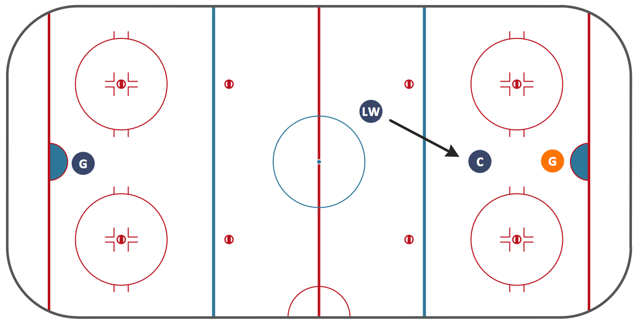
"In ice hockey, a play is offside if a player on the attacking team enters the offensive zone before the puck, unless the puck is sent or carried there by a defending player. When an offside violation occurs, a linesman will stop play. A faceoff is then held at a neutral ice spot closest to the infraction to restart play. ...
The National Hockey League (NHL) and International Ice Hockey Federation (IIHF) apply similar rules for determining offside. A player is judged to be offside if their skates completely cross the blue line dividing their offensive zone from the neutral zone before the puck completely crosses the same line. In both organizations, it is the position of a player's skates that are important. They cannot use their stick or other part of their body to remain onside. The lone caveat to this rule is that an attacking player's skates may precede the puck into the attacking zone when they are skating backwards and if they are in control of the puck." [Offside (ice hockey). Wikipedia]
The ice hockey tactic diagram example "Offside (ice hockey)" was created using the ConceptDraw PRO diagramming and vector drawing software extended with the Hockey solution from the Sport area of ConceptDraw Solution Park.
Ice Hockey Offside Diagram
"Offsides" is a very basic sports term, which can be very hard to explain to a novice. The fundamental concepts in sports can be extremely difficult to convey without a drawing, that's why we included an Offsides Sample in the Hockey solution. Explaining with ConceptDraw in your playbook is easier than ever before!Soccer (Football) Offside
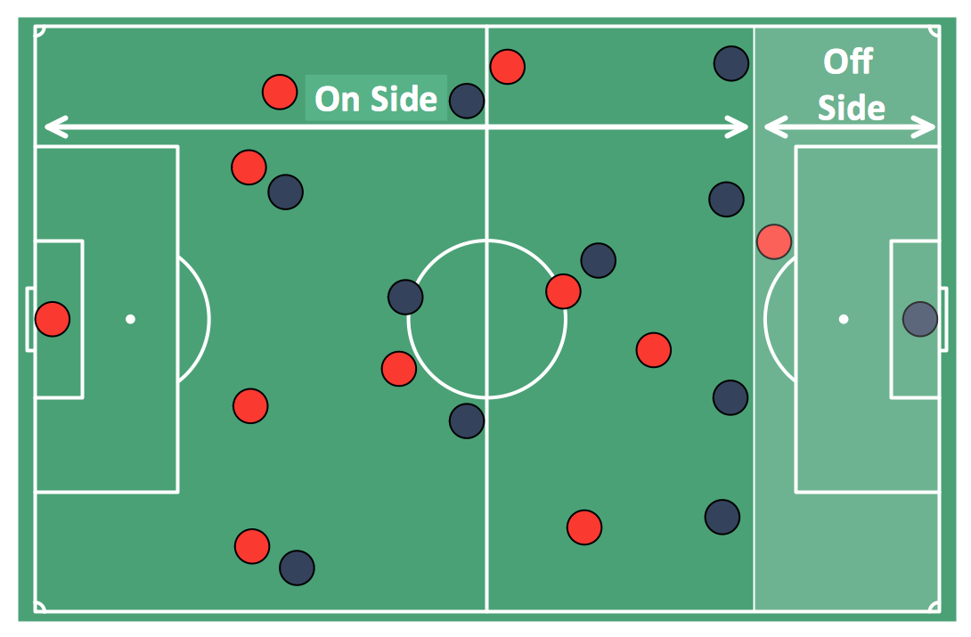
It’s very convenient to explain the different tactics and positions using the visual drawings. ConceptDraw PRO software extended with the Soccer solution from the Sport area of ConceptDraw Solution Park provides libraries, templates and samples allowing specialists or soccer fans to draw the soccer-related diagrams and schemas of any complexity in a few minutes."Offside (sometimes known as offsides) is a law in association football which states that if a player is in an offside position when the ball is touched or played by a team-mate, the player may not become actively involved in the play. A player is in an offside position when closer to the opponent's goal line than both the ball and the second-to-last defender (which is usually the last outfield player), and also in the opponent's half of the pitch. "Offside position" is a matter of fact, whereas committing an "offside offence" occurs when a player is "actively involved" and is subject to the interpretation of the referee. Goals scored after committing an offside offence are nullified if caught by the referee." [Offside (association football). Wikipedia]
The diagram example "Association football (soccer) offside" was created using the ConceptDraw PRO diagramming and vector drawing software extended with the Football solution from the Sport area of ConceptDraw Solution Park.
www.conceptdraw.com/ solution-park/ sport-soccer
The diagram example "Association football (soccer) offside" was created using the ConceptDraw PRO diagramming and vector drawing software extended with the Football solution from the Sport area of ConceptDraw Solution Park.
www.conceptdraw.com/ solution-park/ sport-soccer
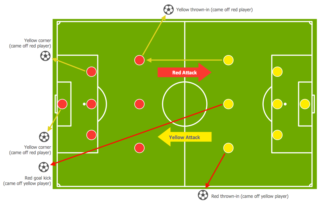
Soccer (Football) Tactics
To quick and easy draw the diagrams with soccer (football) tactics, use the "Soccer (Football) Fields" and "Soccer (Football) Positions" libraries from the Soccer solution from the Sport area of ConceptDraw Solution Park
 Ice Hockey
The Ice Hockey Solution extends the capabilities of ConceptDraw PRO v9.5 (or later) with samples, templates, and libraries of vector objects for drawing hockey diagrams, plays schemas, and illustrations. The Ice Hockey Solution can be used to make polishe
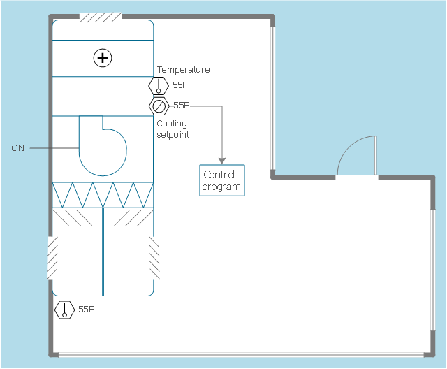
This HVAC floor plan sample illustrates the temperature sensors of air handler digital thermostat control.
"A thermostat is a component of a control system which senses the temperature of a system so that the system's temperature is maintained near a desired setpoint. The thermostat does this by switching heating or cooling devices on or off, or regulating the flow of a heat transfer fluid as needed, to maintain the correct temperature. The name is derived from the Greek words thermos "hot" and statos "a standing".
A thermostat may be a control unit for a heating or cooling system or a component part of a heater or air conditioner. Thermostats can be constructed in many ways and may use a variety of sensors to measure the temperature. The output of the sensor then controls the heating or cooling apparatus. A thermostat may switch on and off at temperatures either side of the setpoint the extent of the difference is known as hysteresis and prevents too frequent switching of the controlled equipment." [Thermostat. Wikipedia]
The HVAC plan example "Digital unit ventilator control" was created using the ConceptDraw PRO diagramming and vector drawing software extended with the HVAC Plans solution from the Building Plans area of ConceptDraw Solution Park.
Basic Flowchart Symbols and Meaning
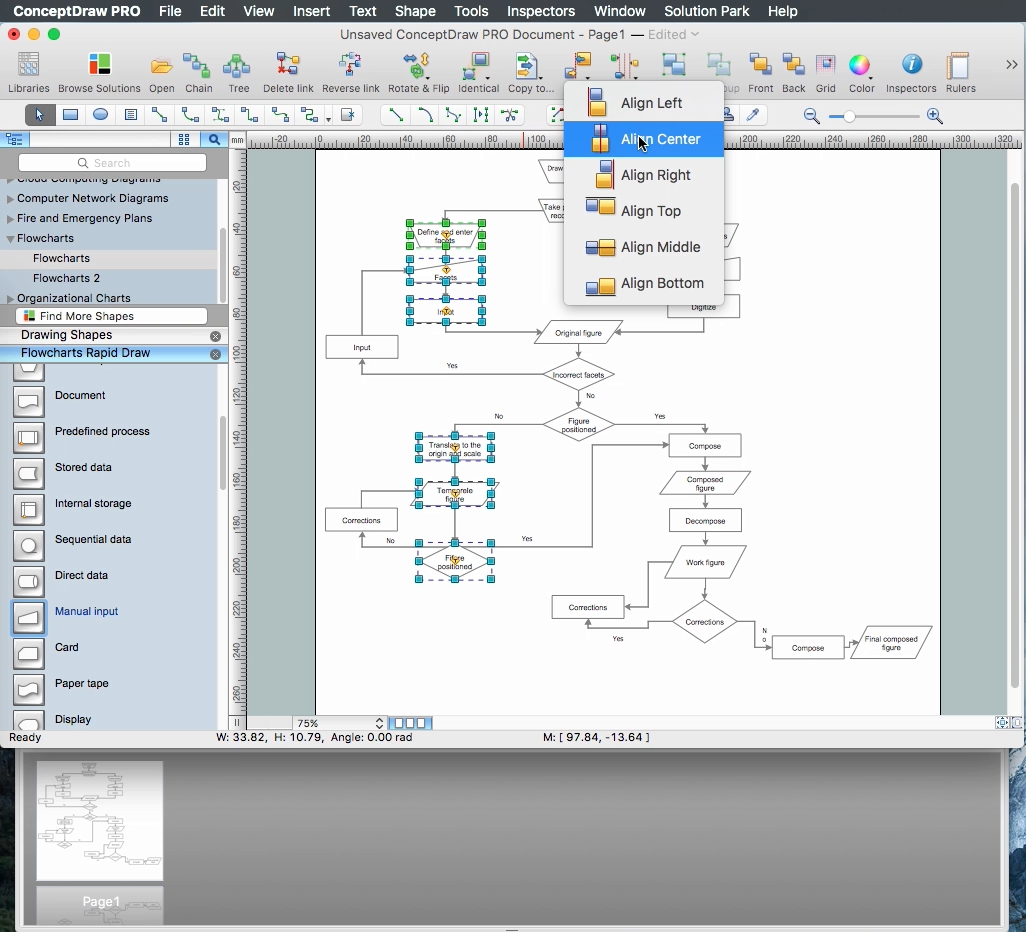
Flowcharts are the best for visually representation the business processes and the flow of a custom-order process through various departments within an organization. ConceptDraw PRO diagramming and vector drawing software extended with Flowcharts solution offers the full set of predesigned basic flowchart symbols which are gathered at two libraries: Flowchart and Flowcharts Rapid Draw. Among them are: process, terminator, decision, data, document, display, manual loop, and many other specific symbols. The meaning for each symbol offered by ConceptDraw gives the presentation about their proposed use in professional Flowcharts for business and technical processes, software algorithms, well-developed structures of web sites, Workflow diagrams, Process flow diagram and correlation in developing on-line instructional projects or business process system. Use of ready flow chart symbols in diagrams is incredibly useful - you need simply drag desired from the libraries to your document and arrange them in required order. There are a few serious alternatives to Visio for Mac, one of them is ConceptDraw PRO. It is one of the main contender with the most similar features and capabilities.
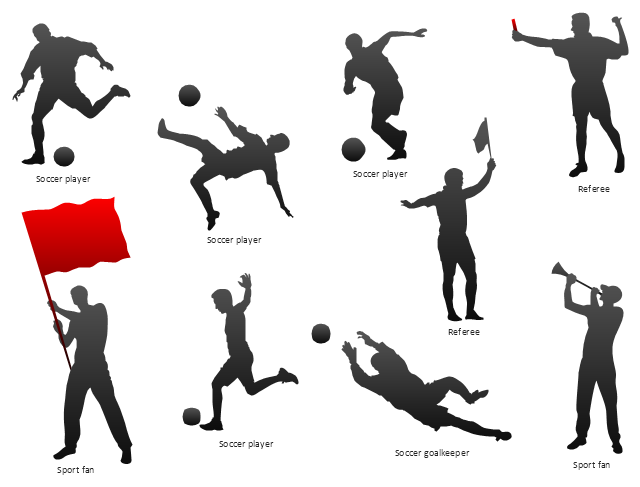
The vector stencils library "Soccer silhouettes" contains 9 association football silhouettes clipart.
"Gameplay.
Association football is played in accordance with a set of rules known as the Laws of the Game. The game is played using a spherical ball (of 71 cm (28 in) circumference in FIFA play), known as the football (or soccer ball). Two teams of eleven players each compete to get the ball into the other team's goal (between the posts and under the bar), thereby scoring a goal. The team that has scored more goals at the end of the game is the winner; if both teams have scored an equal number of goals then the game is a draw. Each team is led by a captain who has only one official responsibility as mandated by the Laws of the Game: to be involved in the coin toss prior to kick-off or penalty kicks.
The primary law is that players other than goalkeepers may not deliberately handle the ball with their hands or arms during play, though they do use their hands during a throw-in restart. Although players usually use their feet to move the ball around, they may use any part of their body (notably, "heading" with the forehead) other than their hands or arms. Within normal play, all players are free to play the ball in any direction and move throughout the pitch, though the ball cannot be received in an offside position." [Association football. Wikipedia]
The clip art example "Design elements - Soccer silhouettes" was created using the ConceptDraw PRO diagramming and vector drawing software extended with the Soccer solution from the Sport area of ConceptDraw Solution Park.
www.conceptdraw.com/ solution-park/ sport-soccer
"In association football, the formation describes how the players in a team are positioned on the pitch. Different formations can be used depending on whether a team wishes to play more attacking or defensive football. ...
The WM system was created in the mid-1920s by Herbert Chapman of Arsenal to counter a change in the offside law in 1925. The change had reduced the number of opposition players that attackers needed between themselves and the goal-line from three to two. This led to the introduction of a centre-back to stop the opposing centre-forward, and tried to balance defensive and offensive playing. The formation became so successful that by the late-1930s most English clubs had adopted the WM. Retrospectively, the WM has either been described as a 3–2–5 or as a 3–4–3, or more precisely a 3–2–2–3 reflecting the letters which symbolised it. The gap in the centre of the formation between the two wing halves and the two inside forwards allowed Arsenal to counter-attack effectively. The W-M was subsequently adapted by several English sides, but none could apply it in quite the same way Chapman had. This was mainly due to the comparative rarity of Alex James in the English game. He was one of the earliest playmakers in the history of the game, and the hub around which Chapman's Arsenal revolved." [Formation (association football). Wikipedia]
The diagram example "Association football (soccer) formation 3-2-5 (WM)" was created using the ConceptDraw PRO diagramming and vector drawing software extended with the Football solution from the Sport area of ConceptDraw Solution Park.
www.conceptdraw.com/ solution-park/ sport-soccer
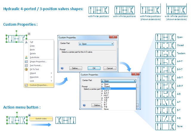
"Directional control valves route the fluid to the desired actuator. They usually consist of a spool inside a cast iron or steel housing. The spool slides to different positions in the housing, and intersecting grooves and channels route the fluid based on the spool's position. The spool has a central (neutral) position maintained with springs; in this position the supply fluid is blocked, or returned to tank. Sliding the spool to one side routes the hydraulic fluid to an actuator and provides a return path from the actuator to tank. When the spool is moved to the opposite direction the supply and return paths are switched. When the spool is allowed to return to neutral (center) position the actuator fluid paths are blocked, locking it in position. Directional control valves are usually designed to be stackable, with one valve for each hydraulic cylinder, and one fluid input supplying all the valves in the stack. Tolerances are very tight in order to handle the high pressure and avoid leaking, spools typically have a clearance with the housing of less than a thousandth of an inch (25 µm). The valve block will be mounted to the machine's frame with a three point pattern to avoid distorting the valve block and jamming the valve's sensitive components. The spool position may be actuated by mechanical levers, hydraulic pilot pressure, or solenoids which push the spool left or right. A seal allows part of the spool to protrude outside the housing, where it is accessible to the actuator. The main valve block is usually a stack of off the shelf directional control valves chosen by flow capacity and performance. Some valves are designed to be proportional (flow rate proportional to valve position), while others may be simply on-off. The control valve is one of the most expensive and sensitive parts of a hydraulic circuit." [Hydraulic machinery. Wikipedia]
The Windows template "Hydraulic 4-ported 3-position valve" for the ConceptDraw PRO diagramming and vector drawing software is included in the Mechanical Engineering solution from the Engineering area of ConceptDraw Solution Park.
www.conceptdraw.com/ solution-park/ engineering-mechanical
The Windows template "Hydraulic 4-ported 3-position valve" for the ConceptDraw PRO diagramming and vector drawing software is included in the Mechanical Engineering solution from the Engineering area of ConceptDraw Solution Park.
www.conceptdraw.com/ solution-park/ engineering-mechanical
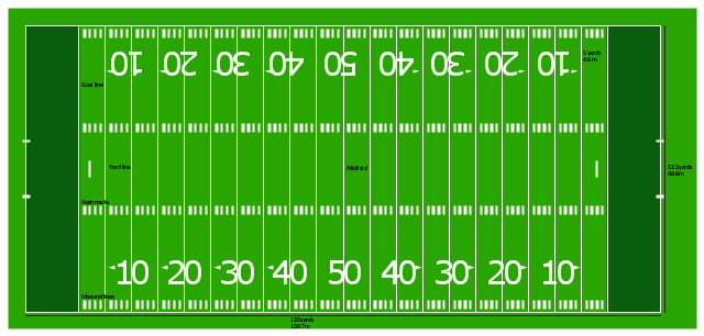
"Football games are played on a rectangular field that measures 120 yards (110 m) long and 53.33 yards (48.76 m) wide. Lines marked along the ends and sides of the field are known respectively as the end lines and side lines, and goal lines are marked 9 yards (8.2 m) outward from each end line. Weighted pylons are placed on the inside corner of the intersections of the goal lines and end lines.
White markings on the field identify the distance from the end zone. Inbound lines, or hash marks, are short parallel lines that mark off 1 yard (0.91 m) increments. Yard lines, which run the width of the field, are marked every 5 yards (4.6 m). A line one yard wide is placed at each end of the field. This line is marked at the center of the two-yard line in professional play and at the three-yard line in college play. Numerals that display the yard lines in multiples of ten are placed along both sides of the field.
Goalposts are at the center of the plane of each of the two end lines. The crossbar of these posts is ten feet (3 meters) above the ground, with vertical uprights at the end of the crossbar 18 feet 6 inches (6 m) apart for professional and collegiate play and 23 feet 4 inches (7 m) apart for high school play. The uprights extend vertically 10 yards on professional fields, a minimum of 10 yards on college fields, and a minimum of ten feet on high school fields. Goal posts are padded at the base, and orange ribbons are normally placed at the tip of each upright." [American football. Wikipedia]
The diagram example "Horizontal colored football field" was created using the ConceptDraw PRO diagramming and vector drawing software extended with the Football solution from the Sport area of ConceptDraw Solution Park.
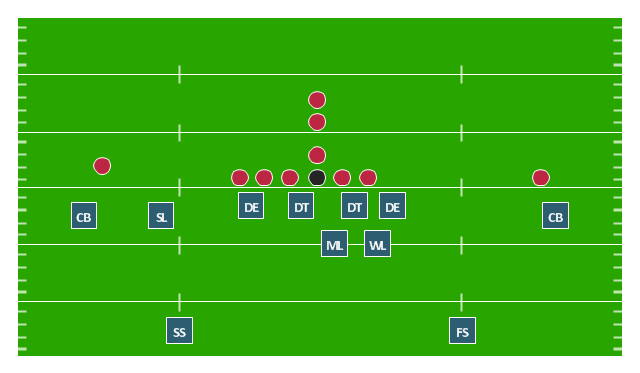
"In American football, a 4–3 defense is a defensive alignment consisting of four down linemen and three linebackers. It is probably the most commonly used defense in modern American football and especially in the National Football League. ...
In the original version of the 4–3, the tackles lined up over the offensive guards and the ends lined up on the outside shoulder of the offensive tackles, with the middle linebacker over the center and the other linebackers outside the ends. In the mid-1960s Hank Stram developed a popular variation, the "Kansas City Stack", which shifted the strong side defensive end over the tight end, stacked the strongside linebacker over the tackle, and shifted the weakside tackle over center. At about the same time the Cleveland Browns frequently used a weakside shift. The Dallas Cowboys coach Tom Landry developed a "flex" variation, in order to take advantage of the quickness of his Hall of Fame tackle, Bob Lilly. In Tom Landry's original 4–3 defenses (4-3 Inside and 4-3 Outside), both defensive tackle were flexed. In the "flex", on a pro set right, with defensive keys showing a run to the right, the right defensive tackle would be flush on the line and was supposed to penetrate. The right defensive end and left defensive tackle were flexed two feet off the line of scrimmage, the right defensive end now head on with the left offensive tackle (i.e. a 4-2-2-5 front instead of the more common 5-2-2-5 front). This gave the defense a "zig zag" look unlike any other of its day. More modern versions of the 4-3 include the Tampa 2 scheme and the 4-3 slide." [4–3 defense. Wikipedia]
The American football positions diagram example "Defensive play - Under front" was created using the ConceptDraw PRO diagramming and vector drawing software extended with the Football solution from the Sport area of ConceptDraw Solution Park.
How to Build a Flowchart
The ConceptDraw PRO is a professional software for quick creating great looking flowcharts. The vector stencils from object libraries allows you to use RapidDraw technology. By the clicking on direction arrows one can add new object to flowcharts. This technology gives to users the ability to fast creating visualization for the structural data. Learn the basics of flowcharting and see how to build create a flowchart using ConceptDraw automatic drawing tools.
 Soccer
The Soccer (Football) Solution extends ConceptDraw PRO v9.5 (or later) software with samples, templates, and libraries of vector objects for drawing soccer (football) diagrams, plays schemas, and illustrations. It can be used to make professional looking
- Soccer (Football) Offside | Soccer (Football) Tactics | Ice Hockey ...
- Soccer (Football) Tactics | Offside (ice hockey) | Deke (ice hockey ...
- Ice Hockey Offside Diagram | Ice Hockey Rink Dimensions | Soccer ...
- Soccer (Football) Tactics | Soccer (Football) Offside | Soccer ...
- Ice Hockey Rink Dimensions | Ice Hockey Offside Diagram | Soccer ...
- Soccer (Football) Formation | Soccer (Football) Offside | Soccer ...
- Soccer (Football) Dimensions | Soccer (Football) Positions | Soccer ...
- Soccer (Football) Formation | Soccer (Football) Positions | Soccer ...
- Ice Hockey Rink Dimensions | Ice Hockey | Ice Hockey Diagram ...
- Basketball Court Diagram and Basketball Positions | Soccer ...
- Offensive Play – Double Wing Wedge – Vector Graphic Diagram ...
- Soccer (Football) Diagram Software | Soccer (Football) Tactics ...
- Soccer (Football) Positions | Soccer (Football) Tactics | Association ...
- Soccer (Football) Illustrated | Offensive Play – Double Wing Wedge ...
- Soccer (Football) Formation | Soccer (Football) Positions | Sport ...
- Football Pitch And Position
- Design elements - Ice hockey positions | Hockey positions - Vector ...
- Offensive Play – Double Wing Wedge – Vector Graphic Diagram ...
- Football | Association football (soccer) - The pitch: throw-ins, goal ...
- Soccer (Football) Positions | How to Make Soccer Position Diagram ...
.png--diagram-flowchart-example.png)
-diagram-association-football-(soccer)-offside.png--diagram-flowchart-example.png)

-formation-diagram-association-football-(soccer)-formation-3-2-5-(wm).png--diagram-flowchart-example.png)
