Restaurant Floor Plans Software

Building Drawing Software for Design Office Layout Plan


Cisco Network Topology. Cisco icons, shapes, stencils and symbols
")
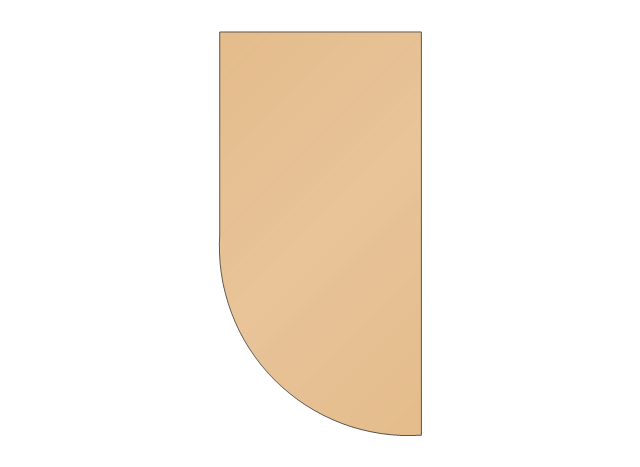
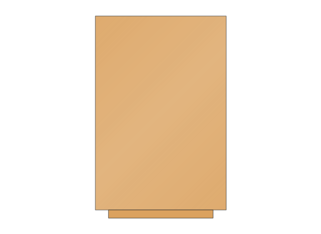
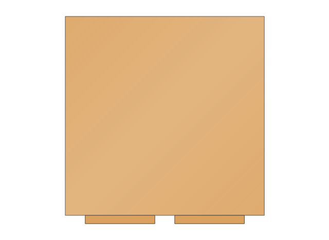
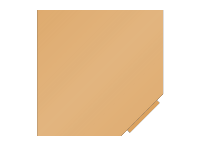
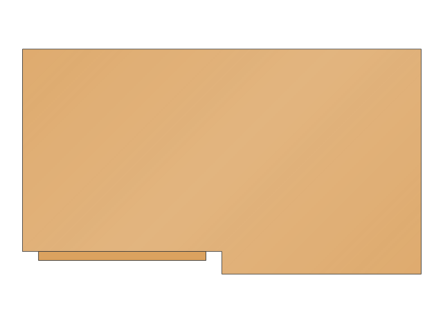
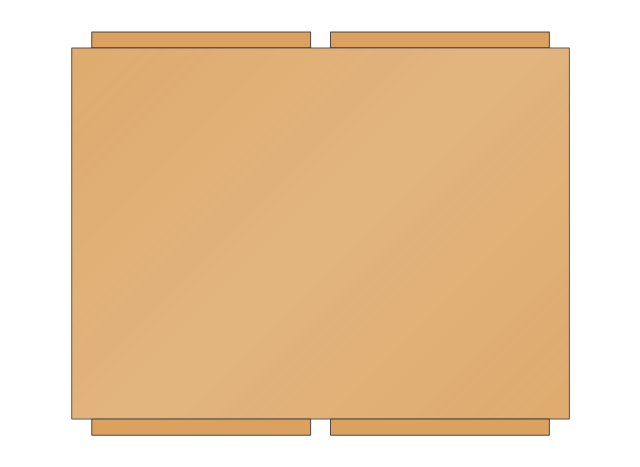
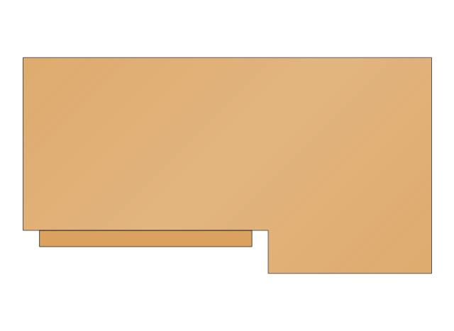
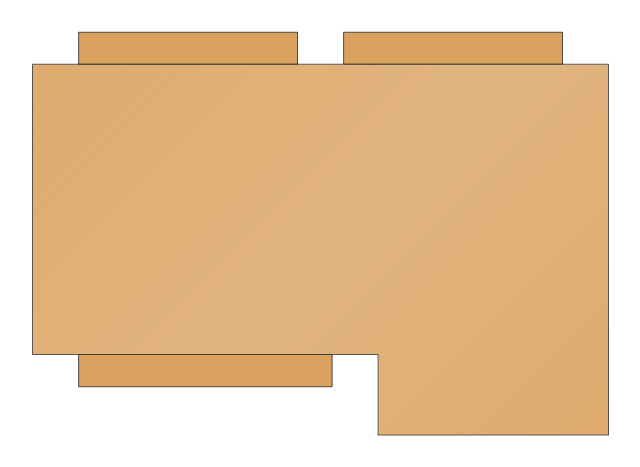
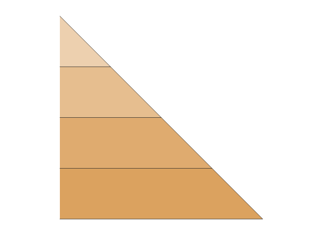
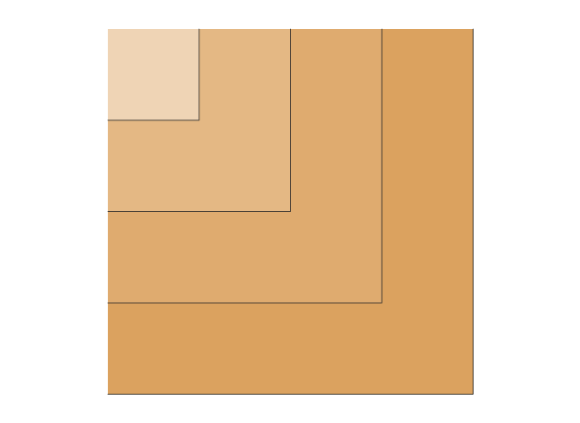
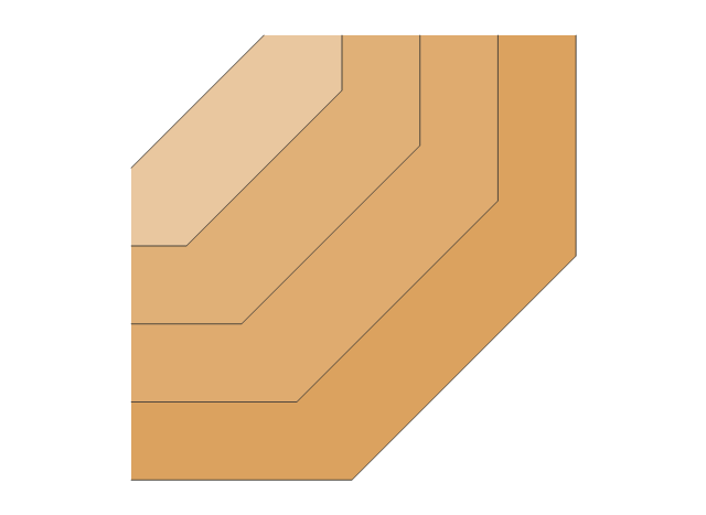
The vector stencils library "Cabinets and bookcases" contains 41 shapes of cabinets and bookcases. Use it for drawing floor plans in the ConceptDraw PRO diagramming and vector drawing software extended with the Floor Plans solution from the Building Plans area of ConceptDraw Solution Park.
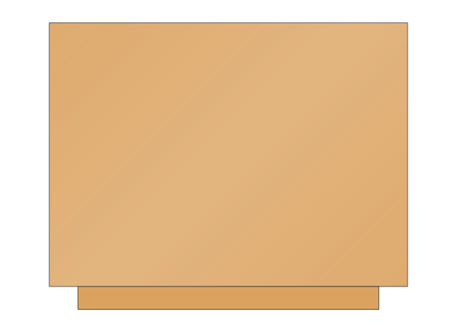
Base End-Shelf
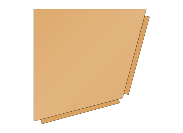
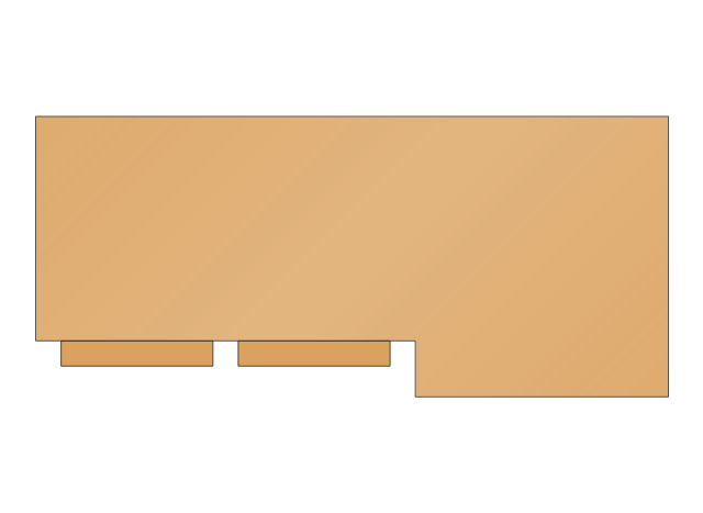
Base 1
Base 2
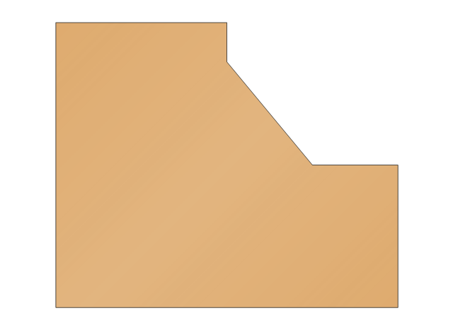
Base Corner
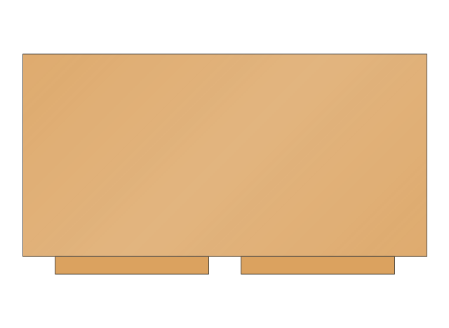
Base blind corner
Base End Angle
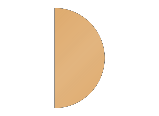
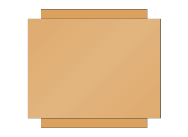
Peninsula End-Shelf
Base Peninsula 1
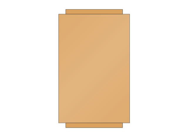
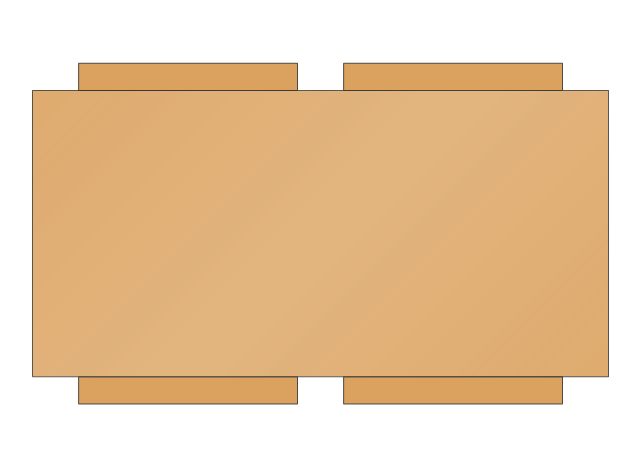
Base Peninsula 2
L-shaped Countertop
Wall end-shelf

Wall 1
Wall 2
Wall Corner

Wall Blind Corner 1
Wall Blind Corner 2
Wall Angle Cabinet

Wall Peninsula 1
Wall Peninsula 2
Wall Blind Peninsula
Track End-Bevel
Track Corner
Track 45 Degree
Tray track, open left
Tray track, open right
Tray track, open left and right
Tray track
Bookcase 1

Bookcase 2
Cabinet 1
Cabinet 2
Cabinet 1, 2 Drawer
Cabinet 1, 3 Drawer
Cabinet 2, 2 Drawer
Cabinet 2, 3 Drawer
Cabinet 2, 2 Drawer and Door
Cabinet 2, 3 Drawer and Door
Cabinet, Under Desk
Cabinet, Under Desk, 2 Drawer
Cabinet, Under Desk, 3 Drawer
File Cabinet
 Office Layout Plans
Office layouts and office plans are a special category of building plans and are often an obligatory requirement for precise and correct construction, design and exploitation office premises and business buildings. Designers and architects strive to make office plans and office floor plans simple and accurate, but at the same time unique, elegant, creative, and even extraordinary to easily increase the effectiveness of the work while attracting a large number of clients.
The vector stencils library "Office pictograms" contains 20 icons of office symbols, stationery, office supplies, writing implement, writing instruments. Use it to draw your business infographics. The example "Office pictograms - Vector stencils library" was created using the ConceptDraw PRO diagramming and vector drawing software extended with the Pictorial infographics solution from the area "What is infographics" in ConceptDraw Solution Park.
Paper

Binder clip

Pencil

Stamp

Scissors

Folder

Office folders

Tie

Coffee cup

File

Envelope

Printer

Paper shredder

Calculator

Armchair

Wastepaper basket

Cabinet

Telephone

Fax

Phone book

The vector stencils library "Cubicles and work surfaces" contains 46 shapes of cubicles and work surfaces. Use these shapes for drawing office floor plans, furniture, equipment and space layouts in the ConceptDraw PRO diagramming and vector drawing software extended with the Office Layout Plans solution from the Building Plans area of ConceptDraw Solution Park.
Straight Workstation

L Workstation

Council Workstation

Cube Workstation

L-shaped Workstation

U-shaped Workstation

Panel Post

Panel

Curved Panel

Cubicle Walls (4 Walls)
-cubicles-and-work-surfaces---vector-stencils-library.png--diagram-flowchart-example.png)
Cubicle Walls (3 Walls)
-cubicles-and-work-surfaces---vector-stencils-library.png--diagram-flowchart-example.png)
Cubicle Walls (2 Walls)
-cubicles-and-work-surfaces---vector-stencils-library.png--diagram-flowchart-example.png)
Corner Desk

Corner Desk with Filing Cabinets

Credenza with Lateral File

Credenza

Credenza with Storage

Work Surface

Desk with Right Hand Return

Desk with Left Hand Return

Cubicle Desk

Round Corner

Work Surface

Corner surface 1

Corner Surface 2

Corner Surface 3

Corner Cut Out Surface 1

Corner Cut Out Surface 2

Extended Corners Surface

Extended Radius Surface (One End)
-cubicles-and-work-surfaces---vector-stencils-library.png--diagram-flowchart-example.png)
Extended Radius Surface (Two Ends)
-cubicles-and-work-surfaces---vector-stencils-library.png--diagram-flowchart-example.png)
Round Surface

Extended Round Surface

Bent Surface

Bullnose Surface

Bevel Surface 1

Bevel Surface 2

Work Peninsula 1

Work Peninsula 2

Pedestal

Storage Unit

Susp Coat Bar/Shelf

Susp Open Shelf

Suspended Lateral File

File Cabinet

Cabinet

The vector stencils library "Office furniture" contains 36 shapes of office furnishings and work surfaces. Use these shapes for drawing floor plans and furniture arrangements and layouts of office suites and conference rooms in the ConceptDraw PRO diagramming and vector drawing software extended with the Office Layout Plans solution from the Building Plans area of ConceptDraw Solution Park.
Multi-Chair Rectangular Table

Multi-Chair Rectangular Table with Rounded Corners

Multi-Chair Round Table

Multi-Chair Boat Shape Table

Desk

Desk with Right Hand Return

Desk with Left Hand Return

Cubicle Desk

Rounded Desk

Credenza

Bookcase

Storage Unit

Round Corner

Work Surface

Corner Surface

File

Lateral File

Flat File

File Cabinet

Podium

Reception Desk

Screen

Desk Mat

Chair with Arms 1

Chair with Arms 2

Side Chair without Arms

Side Chair with Arms

Sectional Sofa with Arms

Sofa 1

Curved Back Sofa

Couch

Sofa 2

Paper Tray

Backboard

Marker Board

Chalkboard

The vector stencils library "Rack diagrams" contains 33 rack design elements for drawing the computer network server rack diagrams.
"A 19-inch rack is a standardized frame or enclosure for mounting multiple equipment modules. Each module has a front panel that is 19 inches (482.6 mm) wide, including edges or ears that protrude on each side which allow the module to be fastened to the rack frame with screws. ...
Equipment designed to be placed in a rack is typically described as rack-mount, rack-mount instrument, a rack mounted system, a rack mount chassis, subrack, rack mountable, or occasionally simply shelf. The height of the electronic modules is also standardized as multiples of 1.75 inches (44.45 mm) or one rack unit or U (less commonly RU). The industry standard rack cabinet is 42U tall. ...
19-inch racks in 2-post or 4-post form hold most equipment in modern data centers, ISP facilities and professionally designed corporate server rooms. They allow for dense hardware configurations without occupying excessive floorspace or requiring shelving." [19-inch rack. Wikipedia]
The clip art example "Rack diagrams - Vector stencils library" was created using the ConceptDraw PRO diagramming and vector drawing software extended with the Rack Diagrams solution from the Computer and Networks area of ConceptDraw Solution Park.
19 inch Rack with Rails

Rack

Rack rails

Rack rails (half-width)
-rack-diagrams---vector-stencils-library.png--diagram-flowchart-example.png)
Single rack rail

Xserve RAID

XServe

1U tray

1U spacer

2U server

1U Ethernet Switch/Hub

2U Ethernet Switch/Hub

1U power strip

1U KVM switch

1U patch panel

Rackmount UPS

Cisco switch (WS-C3560-24PS-S)
-rack-diagrams---vector-stencils-library.png--diagram-flowchart-example.png)
Cisco switch (WS-C3560-48TS-S)
-rack-diagrams---vector-stencils-library.png--diagram-flowchart-example.png)
Cisco switch (WS-C2960-48TT-L)
-rack-diagrams---vector-stencils-library.png--diagram-flowchart-example.png)
Cisco switch (WS-C2960-48TC-L)
-rack-diagrams---vector-stencils-library.png--diagram-flowchart-example.png)
Cisco switch (WS-C2960-24TT-L)
-rack-diagrams---vector-stencils-library.png--diagram-flowchart-example.png)
Cisco switch (WS-C2960-24TC-L)
-rack-diagrams---vector-stencils-library.png--diagram-flowchart-example.png)
7U rackmount LCD monitor

8U rackmount LCD monitor

Fiber optic patch panel (type A)
-rack-diagrams---vector-stencils-library.png--diagram-flowchart-example.png)
Fiber optic patch panel (type B)
-rack-diagrams---vector-stencils-library.png--diagram-flowchart-example.png)
Fiber optic patch panel (type C)
-rack-diagrams---vector-stencils-library.png--diagram-flowchart-example.png)
3U server

2U RAID array

3U RAID array

Managed UPS

1U 19'' LCD monitor keyboard

1U server

The vector stencils library "Cisco network topology" contains 89 symbols of Cisco network devices and design elements for drawing computer network topology diagrams.
"There are two basic categories of network topologies:
(1) Physical topologies,
(2) Logical topologies.
The shape of the cabling layout used to link devices is called the physical topology of the network. This refers to the layout of cabling, the locations of nodes, and the interconnections between the nodes and the cabling. The physical topology of a network is determined by the capabilities of the network access devices and media, the level of control or fault tolerance desired, and the cost associated with cabling or telecommunications circuits.
The logical topology in contrast, is the way that the signals act on the network media, or the way that the data passes through the network from one device to the next without regard to the physical interconnection of the devices." [Network topology. Wikipedia]
The symbols example "Cisco network topology - Vector stencils library" was created using the ConceptDraw PRO diagramming and vector drawing software extended with the Cisco Network Diagrams solution from the Computer and Networks area of ConceptDraw Solution Park.
www.conceptdraw.com/ solution-park/ computer-networks-cisco
Router

Broadband router

Router firewall

Wireless router

Workgroup switch

ATM switch

ISDN switch

Multilayer switch

Protocol translator

Communications server

Transpath

Bridge

Terminal server

Route switch processor

Content engine (cache director)
-cisco-network-topology---vector-stencils-library.png--diagram-flowchart-example.png)
Management engine (ME 1100)
-cisco-network-topology---vector-stencils-library.png--diagram-flowchart-example.png)
Switch processor

ITP

Voice gateway

BBSM

ATA

SIP Proxy server

NetRanger

Cisco 1000

IP

System controller

ACE

Directory server

ADM

Cisco Unity Express

Unity server

Cisco security

CallManager

DSLAM

H.323

CDM (Content Distribution Manager)
-cisco-network-topology---vector-stencils-library.png--diagram-flowchart-example.png)
ICM

Access point

Wireless bridge

Wireless connectivity

Guard

Mobile access router

Carrier Routing System (CRS)
-cisco-network-topology---vector-stencils-library.png--diagram-flowchart-example.png)
Vault

Workstation

PC

Macintosh

Cloud, gold

Cloud, white

Cloud, standard color

Cisco security management

PBX

DPT

Government building

Headquarters, blue

Router in building

Man

Woman

Workgroup switch, subdued

Router, subdued

File server

Firewall, horizontal

Firewall, vertical

Firewall, vertical, subdued

Lock

Key

Lock and key

Car

Truck

File cabinet

Breakout box

Breakout box, blue

Host

Relational database

Modem

BBS (Bulletin Board System)
-cisco-network-topology---vector-stencils-library.png--diagram-flowchart-example.png)
Satellite

Satellite dish

UPS

RPS

MAU

PAD

PAD X.28

Diskette

Contact center

Page icon
Antenna

Antenna, blue

Radio tower

 Floor Plans
Construction, repair and remodeling of the home, flat, office, or any other building or premise begins with the development of detailed building plan and floor plans. Correct and quick visualization of the building ideas is important for further construction of any building.
- Photo Cabinet Software Download
- Cabinet Design Software | Office Ideas | Network Diagramming ...
- Cad Software For Cabinets
- Network Diagramming Software for Design Rack Diagrams | Cad ...
- Network Diagramming Software for Design Rack Diagrams | Cabinet ...
- Cabinet Design Software
- Network diagrams with ConceptDraw PRO | Software Diagram ...
- Technology - Vector stencils library | How To use House Electrical ...
- How To Create Restaurant Floor Plan in Minutes | Store Layout ...
- Cabinet Design Software | Network Diagramming Software for ...
- Network Diagramming Software for Design Rack Diagrams | Design ...
- Server Rack Cabinet Vector
- Design elements - Cabinets and bookcases | Cabinets and ...
- Audio, Video, Media | Cinema video and audio equipment layout ...
- Server hardware - Rack diagram | UML component diagram - Start ...
- Network Printer | Building Drawing Software for Design Office Layout ...
- Office furniture - Vector stencils library | Building Drawing Software ...
- How To use House Electrical Plan Software | Design elements ...
- How To Create Restaurant Floor Plan in Minutes | Restaurant ...
- Building Drawing Software for Design Office Layout Plan | Office ...