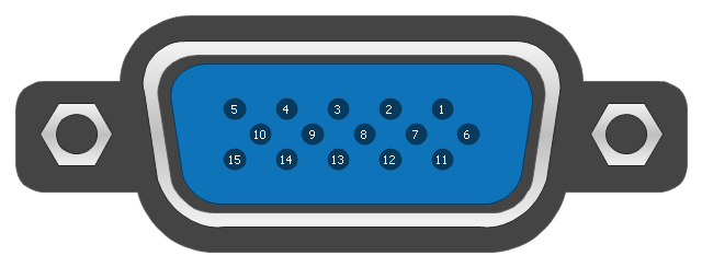
This pinout diagram example showing a VGA connector (as viewed from the socket) was redesigned from the Wikimedia Commons file: DE15 Connector Pinout.svg. [commons.wikimedia.org/ wiki/ File:DE15_ Connector_ Pinout.svg]
"A Video Graphics Array (VGA) connector is a three-row 15-pin DE-15 connector. The 15-pin VGA connector is found on many video cards, computer monitors, and high definition television sets. On laptop computers or other small devices, a mini-VGA port is sometimes used in place of the full-sized VGA connector.
DE-15 is also conventionally called RGB connector, D-sub 15, mini sub D15, mini D15, DB-15, HDB-15, HD-15 or HD15 (High Density, to distinguish it from the older and less flexible DE-9 connector used on some older VGA cards, which has the same shell size but only two rows of pins).
VGA connectors and cables carry analog component RGBHV (red, green, blue, horizontal sync, vertical sync) video signals, and VESA Display Data Channel (VESA DDC) data. In the original version of DE-15 pinout, one pin was keyed by plugging the female connector hole; this prevented non-VGA 15 pin cables from being plugged into a VGA socket. Four pins carried Monitor ID bits which were rarely used; VESA DDC redefined some of these pins and replaced the key pin with +5 V DC power supply.
The VGA interface is not engineered to be hotpluggable (so that the user can connect or disconnect the output device while the host is running), although in practice this can be done and usually does not cause damage to the hardware or other problems. However, nothing in the design ensures that the ground pins make a connection first and break last, so hotplugging may introduce surges in signal lines which may or may not be adequately protected against. Also, depending on the hardware and software, detecting a monitor being connected might not work properly in all cases." [VGA connector. Wikipedia]
The pinout diagram example "VGA connector pinout" was created using the ConceptDraw PRO diagramming and vector drawing software extended with the Audio and Video Connectors solution from the Engineering area of ConceptDraw Solution Park.
The vector stencils library "Application" contains 40 icons of software applications.
Use it to design your computer and telecom illustrations and infographics with ConceptDraw PRO diagramming and vector drawing software.
The vector stencils library "Application" is included in the Computers and Communications solution from the Illustration area of ConceptDraw Solution Park.
Use it to design your computer and telecom illustrations and infographics with ConceptDraw PRO diagramming and vector drawing software.
The vector stencils library "Application" is included in the Computers and Communications solution from the Illustration area of ConceptDraw Solution Park.
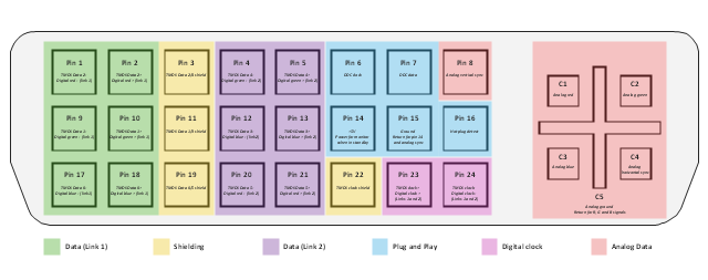
This AV connector pinout diagram example was redesigned from the file: DVI pinout.svg. [en.wikipedia.org/ wiki/ File:DVI_ pinout.svg]
"In electronics, a pinout (sometimes written "pin-out") is a cross-reference between the contacts, or pins, of an electrical connector or electronic component, and their functions. ...
The functions of contacts in electrical connectors, be they power- or signaling-related, must be specified in order for connectors to be interchangeable. When connected, each contact of a connector must mate with the contact on the other connector that has the same function. If contacts of disparate functions are allowed to make contact, the connection may fail and damage may result. Therefore, pinouts are a vital reference when building and testing connectors, cables, and adapters." [Pinout. Wikipedia]
The example "DVI pinout diagram" was created using the ConceptDraw PRO diagramming and vector drawing software extended with the Audio and Video Connectors solution from the Engineering area of ConceptDraw Solution Park.
The vector stencils library "Application" contains 40 icons of software applications.
Use it to design your computer and telecom illustrations and infographics with ConceptDraw PRO diagramming and vector drawing software.
The vector stencils library "Application" is included in the Computers and Communications solution from the Illustration area of ConceptDraw Solution Park.
Use it to design your computer and telecom illustrations and infographics with ConceptDraw PRO diagramming and vector drawing software.
The vector stencils library "Application" is included in the Computers and Communications solution from the Illustration area of ConceptDraw Solution Park.
The vector stencils library "Education pictograms" contains 128 education pictograms. Use this flat icon set to design your educational infogram in ConceptDraw PRO diagramming and vector drawing software.
The vector stencils library "Education pictograms" is included in the Education Infographics solution from the Business Infographics area of ConceptDraw Solution Park.
The vector stencils library "Education pictograms" is included in the Education Infographics solution from the Business Infographics area of ConceptDraw Solution Park.
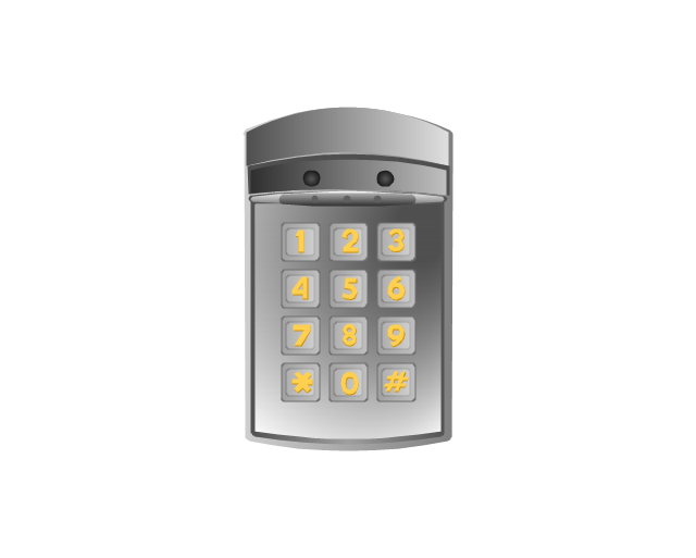
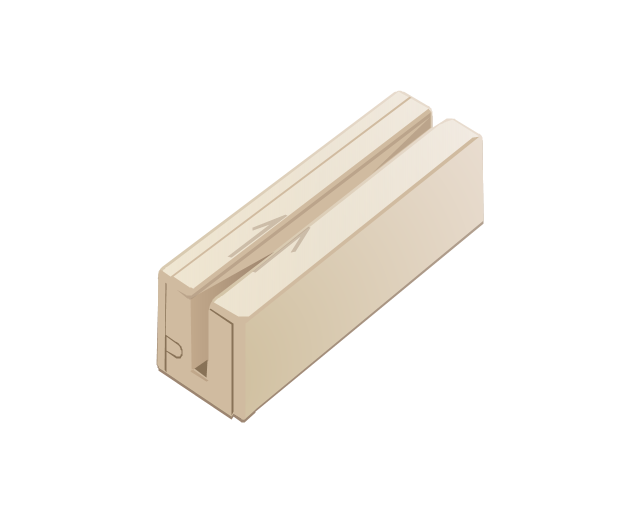
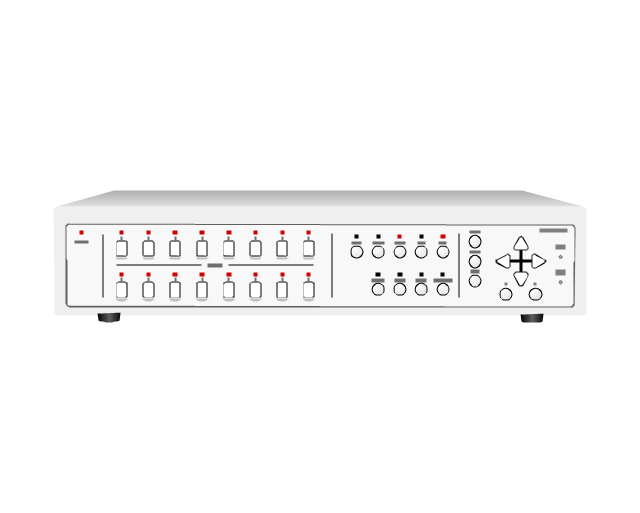
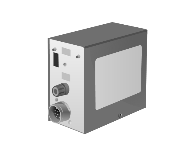
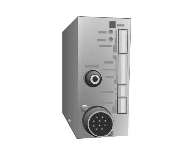
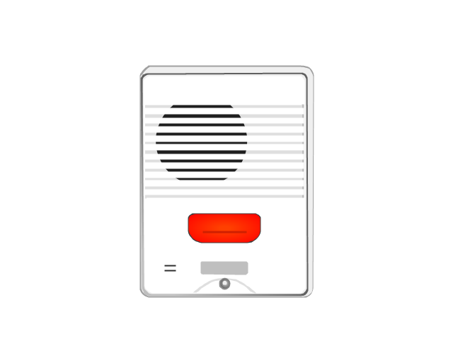
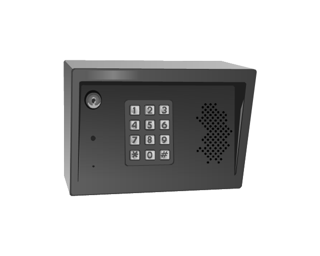
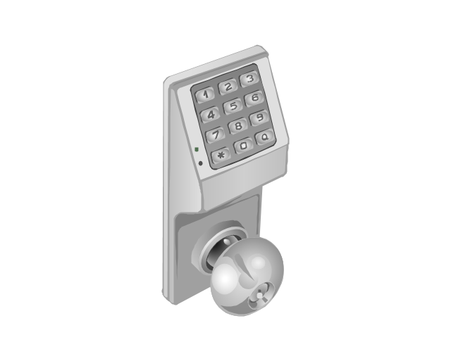
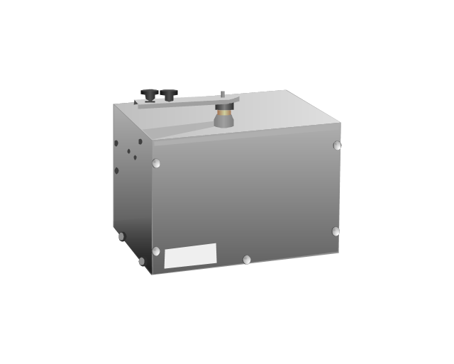
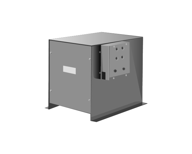
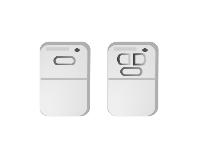
The vector stencils library "Access and security" contains 17 clipart images of access control and security system equipment which you can easy use in your diagrams and illustrations.
"Physical security describes security measures that are designed to deny unauthorized access to facilities, equipment and resources, and to protect personnel and property from damage or harm (such as espionage, theft, or terrorist attacks). Physical security involves the use of multiple layers of interdependent systems which include CCTV surveillance, security guards, protective barriers, locks, access control protocols, and many other techniques." [Physical security. Wikipedia]
The clip art example "Access and security - Vector stencils library" was created in the ConceptDraw PRO diagramming and vector drawing software using the Presentation Clipart solution from the Illustration area of ConceptDraw Solution Park.
www.conceptdraw.com/ solution-park/ illustrations-presentation-clipart
This AV connector pinout diagram example was redesigned from the Wikipedia file: DVI Connector Types.svg.
[en.wikipedia.org/ wiki/ File:DVI_ Connector_ Types.svg]
"Digital Visual Interface (DVI) is a video display interface developed by the Digital Display Working Group (DDWG). The digital interface is used to connect a video source to a display device, such as a computer monitor. It was developed with the intention of creating an industry standard for the transfer of digital video content.
The interface is designed to transmit uncompressed digital video and can be configured to support multiple modes such as DVI-D (digital only), DVI-A (analog only), or DVI-I (digital and analog). Featuring support for analog connections, the DVI specification is compatible with the VGA interface. This compatibility, along with other advantages, led to its widespread acceptance over competing digital display standards Plug and Display (P&D) and Digital Flat Panel (DFP). Although DVI is predominantly associated with computers, it is sometimes used in other consumer electronics such as television sets, video game consoles and DVD players." [Digital Visual Interface. Wikipedia]
The example "DVI connector types" was created using the ConceptDraw PRO diagramming and vector drawing software extended with the Audio and Video Connectors solution from the Engineering area of ConceptDraw Solution Park.
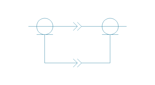
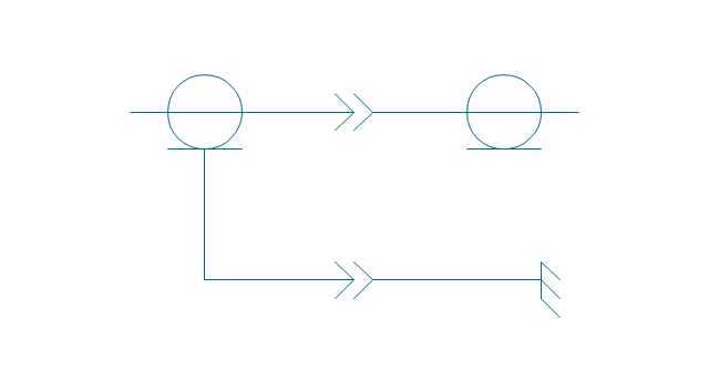
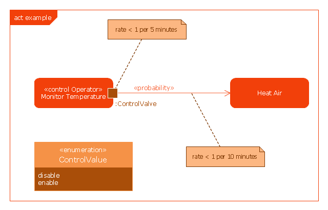
This example was drawn on the base of SysML activity diagram on the page 8 of "SysML Modelling Language explained" document from the Official OMG SysML site.
"The activity diagram represents steps of a process, often making use of “input and output pins” that respectively correspond to the element type required as the input of an activity or action, and the element generated as an output.
If an action or activity corresponds to a block operation, it is possible to ensure that the types of the input and output of this activity are consistent with the block operation signature.
All the activity diagrams definitions used in UML also apply to SysML.
SysML has added a couple of extensions:
- With UML, control can only enable actions to start. SysML extends control to support disabling of actions that are already executing.
- Definition of the flow rate : continuous or discrete
- Definition of the rate and probability on the control or object flows"
[omgsysml.org/ SysML_ Modelling_ Language_ explained-finance.pdf]
The example "SysML activity diagram" was drawn using the ConceptDraw PRO diagramming and vector drawing software extended with the SysML solution from the Software Development area of ConceptDraw Solution Park.
Electrical Symbols — Terminals and Connectors
An electrical connector, is an electro-mechanical device used to join electrical terminations and create an electrical circuit. Electrical connectors consist of plugs (male-ended) and jacks (female-ended). The connection may be temporary, as for portable equipment, require a tool for assembly and removal, or serve as a permanent electrical joint between two wires or devices. 26 libraries of the Electrical Engineering Solution of ConceptDraw DIAGRAM make your electrical diagramming simple, efficient, and effective. You can simply and quickly drop the ready-to-use objects from libraries into your document to create the electrical diagram.This AV connector pinout diagram example was redesigned from the Wikipedia file: DVI Connector Types.svg.
[en.wikipedia.org/ wiki/ File:DVI_ Connector_ Types.svg]
"Digital Visual Interface (DVI) is a video display interface developed by the Digital Display Working Group (DDWG). The digital interface is used to connect a video source to a display device, such as a computer monitor. It was developed with the intention of creating an industry standard for the transfer of digital video content.
The interface is designed to transmit uncompressed digital video and can be configured to support multiple modes such as DVI-D (digital only), DVI-A (analog only), or DVI-I (digital and analog). Featuring support for analog connections, the DVI specification is compatible with the VGA interface. This compatibility, along with other advantages, led to its widespread acceptance over competing digital display standards Plug and Display (P&D) and Digital Flat Panel (DFP). Although DVI is predominantly associated with computers, it is sometimes used in other consumer electronics such as television sets, video game consoles and DVD players." [Digital Visual Interface. Wikipedia]
The example "DVI connector types" was created using the ConceptDraw PRO diagramming and vector drawing software extended with the Audio and Video Connectors solution from the Engineering area of ConceptDraw Solution Park.
ConceptDraw Arrows10 Technology
You can use text with any conceptDraw connectors to describe relationships between objects. Add text to connectors the same way you add text to any object - doubleclick a connector and type.This example show famous Benko Gambit.
"The Benko Gambit (or Volga Gambit) is a chess opening characterised by the move 3...b5 in the Benoni Defense arising after:
1. d4 Nf6
2. c4 c5
3. d5 b5
...
The main line continues with the moves 4. cxb5 a6 5. bxa6 Bxa6 followed by Black fianchettoing the f8-bishop. (Black players leery of the double-fianchetto system, where White plays g3 and b3, and fianchettos both bishops, have preferred 5...g6 intending 6.b3 Bg7 7.Bb2 Nxa6! The point is that it is awkward for White to meet the threat of ...Nb4, hitting d5 and a2, when Nc3 may often be met by ...Nfxd5 because of the latent pin down the long diagonal.) Black's compensation for the pawn takes several forms. First, White, who is already behind in development, must solve the problem of developing the f1-bishop. After 6. Nc3 d6, if White plays 7.e4, then Black will play 7...Bxf1, and after recapturing with the king, White will have to spend time castling artificially with g3 and Kg2, as in the line 7...Bxf1 8.Kxf1 g6 9.g3 Bg7 10.Kg2. If White avoids this by fianchettoing the bishop, it will be in a rather passive position, being blocked by White's own pawn on d5." [Benko Gambit. Wikipedia].
This AV connector pinout diagram example was redesigned from the Wikipedia file: DVI Connector Types.svg.
[en.wikipedia.org/ wiki/ File:DVI_ Connector_ Types.svg]
"Digital Visual Interface (DVI) is a video display interface developed by the Digital Display Working Group (DDWG). The digital interface is used to connect a video source to a display device, such as a computer monitor. It was developed with the intention of creating an industry standard for the transfer of digital video content.
The interface is designed to transmit uncompressed digital video and can be configured to support multiple modes such as DVI-D (digital only), DVI-A (analog only), or DVI-I (digital and analog). Featuring support for analog connections, the DVI specification is compatible with the VGA interface. This compatibility, along with other advantages, led to its widespread acceptance over competing digital display standards Plug and Display (P&D) and Digital Flat Panel (DFP). Although DVI is predominantly associated with computers, it is sometimes used in other consumer electronics such as television sets, video game consoles and DVD players." [Digital Visual Interface. Wikipedia]
The example "DVI connector types" was created using the ConceptDraw PRO diagramming and vector drawing software extended with the Audio and Video Connectors solution from the Engineering area of ConceptDraw Solution Park.
[en.wikipedia.org/ wiki/ File:DVI_ Connector_ Types.svg]
"Digital Visual Interface (DVI) is a video display interface developed by the Digital Display Working Group (DDWG). The digital interface is used to connect a video source to a display device, such as a computer monitor. It was developed with the intention of creating an industry standard for the transfer of digital video content.
The interface is designed to transmit uncompressed digital video and can be configured to support multiple modes such as DVI-D (digital only), DVI-A (analog only), or DVI-I (digital and analog). Featuring support for analog connections, the DVI specification is compatible with the VGA interface. This compatibility, along with other advantages, led to its widespread acceptance over competing digital display standards Plug and Display (P&D) and Digital Flat Panel (DFP). Although DVI is predominantly associated with computers, it is sometimes used in other consumer electronics such as television sets, video game consoles and DVD players." [Digital Visual Interface. Wikipedia]
The example "DVI connector types" was created using the ConceptDraw PRO diagramming and vector drawing software extended with the Audio and Video Connectors solution from the Engineering area of ConceptDraw Solution Park.
 MindTweet
This solution extends ConceptDraw MINDMAP software with the ability to brainstorm, review and organize the sending of Tweets.
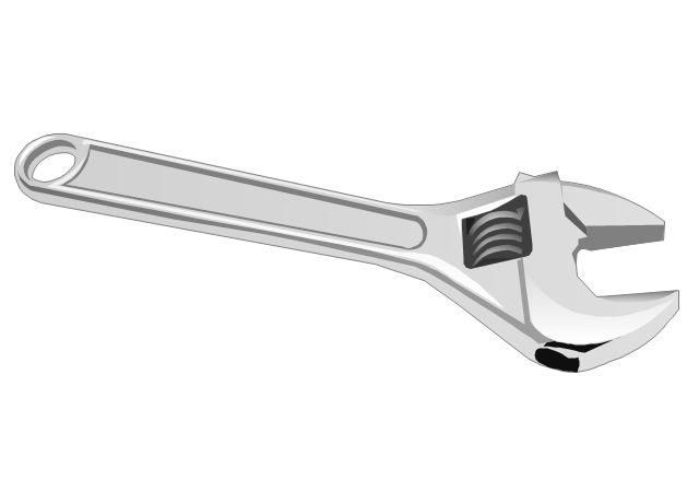
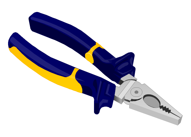
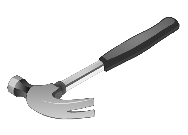
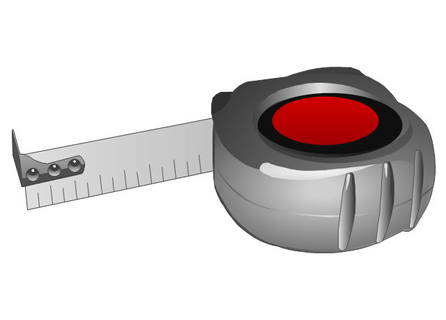
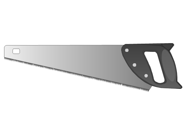
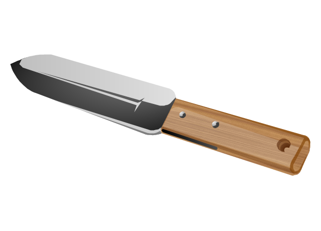
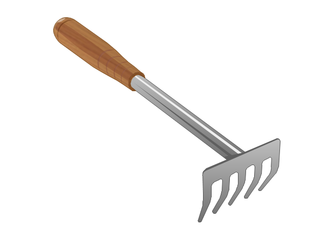
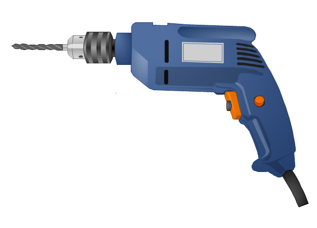
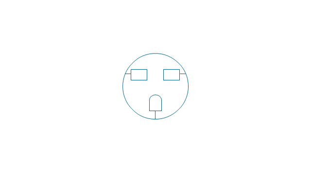
The vector stencils library "Tools" contains 11 clipart images of hand tools and instruments for drawing illustrations.
"A tool is any physical item that can be used to achieve a goal, especially if the item is not consumed in the process. Informally the word is also used to describe a procedure or process with a specific purpose. Tool use by humans dates back millions of years, and other animals are also known to employ simple tools.
Tools that are used in particular fields or activities may have different designations such as "instrument", "utensil", "implement", "machine", or "apparatus". The set of tools needed to achieve a goal is "equipment". The knowledge of constructing, obtaining and using tools is technology." [Tool. Wikipedia]
The clip art example "Tools - Vector stencils library" was created in ConceptDraw PRO diagramming and vector drawing software using the Manufacturing and Maintenance solution from the Illustration area of ConceptDraw Solution Park.
The vector stencils library "Education pictograms" contains 128 education pictograms. Use this flat icon set to design your educational infogram in ConceptDraw PRO diagramming and vector drawing software.
The vector stencils library "Education pictograms" is included in the Education Infographics solution from the Business Infographics area of ConceptDraw Solution Park.
The vector stencils library "Education pictograms" is included in the Education Infographics solution from the Business Infographics area of ConceptDraw Solution Park.
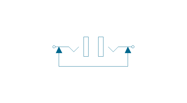
The vector stencils library "Terminals and connectors" contains 43 element symbols of terminals, connectors, plugs, polarized connectors, jacks, coaxial cables, and conductors.
Use it for drawing the wiring diagrams, electrical layouts, electronic schematics, and circuit diagrams in the ConceptDraw PRO diagramming and vector drawing software extended with the Electrical Engineering solution from the Engineering area of ConceptDraw Solution Park.
www.conceptdraw.com/ solution-park/ engineering-electrical
Audio Connectors
Audio connectors are electrical connectors designed and used for audio frequencies. ConceptDraw DIAGRAM diagramming and vector drawing software extended with Audio and Video Connectors Solution from the Industrial Engineering Area is the best for drawing various audio schematics with detailed illustration the audio connectors.- Ceiling Pin Light Symbol
- VGA connector pinout | 15 Pin Vga Cable Wiring Diagram
- DVI pinout diagram | Electrical Symbols — Terminals and ...
- Application - Vector stencils library
- Vga Cable Wiring Diagram 15 Pin
- VGA connector pinout | Terminals and connectors - Vector stencils ...
- VGA connector pinout | Electrical Symbols, Electrical Diagram ...
- VGA connector pinout | Standard Universal Audio & Video ...
- DVI pinout diagram | VGA connector pinout | Audio and Video ...
- An Activity Diagram To Change Pin In An Atm Machine
- VGA connector pinout | Audio and Video Connectors | DVI connector ...
- ConceptDraw OFFICE 5 Delivers Innovative Features and Tools in ...
- VGA connector pinout | Design elements - UML class diagrams ...
- Push pins
- Access and security - Vector stencils library
- DVI connector types
- Electrical Symbols, Electrical Diagram Symbols | Electrical Symbols ...
- DVI pinout diagram | DVI connector types | Audio and Video ...
- Male DVI connector pins (view of plug)































































































-dvi-connector-types.png--diagram-flowchart-example.png)

.png--diagram-flowchart-example.png)
