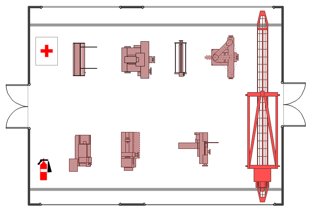
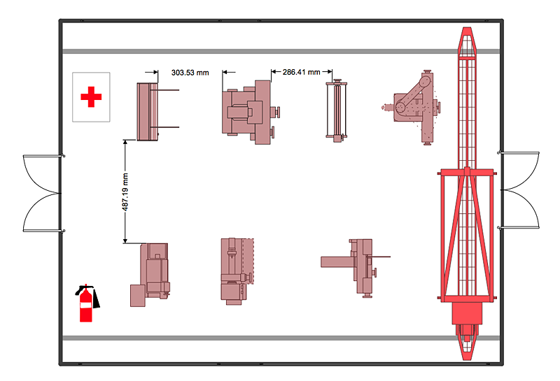
The example "Factory layout floor plan" shows manufacturing machines and equipment in the plant warehouse.
"A factory (previously manufactory) or manufacturing plant is an industrial site, usually consisting of buildings and machinery, or more commonly a complex having several buildings, where workers manufacture goods or operate machines processing one product into another.
Most modern factories have large warehouses or warehouse-like facilities that contain heavy equipment used for assembly line production. Large factories tend to be located with access to multiple modes of transportation, with some having rail, highway and water loading and unloading facilities." [Factory. Wikipedia]
The example "Factory layout floor plan" was created using the ConceptDraw PRO diagramming and vector drawing software extended with the Plant Layout Plans solution from the Building Plans area of ConceptDraw Solution Park.
 Plant Layout Plans
This solution extends ConceptDraw PRO v.9.5 plant layout software (or later) with process plant layout and piping design samples, templates and libraries of vector stencils for drawing Plant Layout plans. Use it to develop plant layouts, power plant desig
 Building Plans Area
The Building Plans Area collects solutions for drawing the building and site plans.
HelpDesk
How to Create a Plant Layout Design
A plant construction process begins from a plant layout stage - an engineering stage used to design, analyze and finally choose the suitable configurations for a manufacturing plant. Plant Layout issues are core to any enterprise and are challenged in all types of manufacturing process. The sufficiency of layout influences the efficiency of subsequent operations. It is an important background for efficient manufacturing and also has a great deal with many questions. Once the place of the plant has been determined, the next important task before the management of the plant is to plan appropriate layout for the enterprise. Plant layout is used to create the most effective physical arrangement of machinery and equipment, with the plant building in such a manner so as to make quickest and cheapest way from a raw material to the shipment of the completed product Making a plan that shows the location of industrial equipment involves many different elements that can be managed using ConThe vector stencils library "Machines and equipment" contains 24 symbols of industrial machines and equipment.
Use the design elements library "Machines and equipment" for drawing plant interior design plans, manufacturing equipment layouts and factory floor plans using the ConceptDraw PRO diagramming and vector drawing software.
"Manufacturing is the production of goods for use or sale using labor and machines, tools, chemical and biological processing, or formulation. The term may refer to a range of human activity, from handicraft to high tech, but is most commonly applied to industrial production, in which raw materials are transformed into finished goods on a large scale.
Modern manufacturing includes all intermediate processes required for the production and integration of a product's components. Some industries, such as semiconductor and steel manufacturers use the term fabrication instead.
The manufacturing sector is closely connected with engineering and industrial design." [Manufacturing. Wikipedia]
The shapes library "Machines and equipment" is included in the Plant Layout Plans solution from the Building Plans area of ConceptDraw Solution Park.
Design Element: Rack Diagram for Network Diagrams
ConceptDraw PRO is perfect for software designers and software developers who need to draw Rack Diagrams.
 Computer Network Diagrams
Computer Network Diagrams solution extends ConceptDraw PRO software with samples, templates and libraries of vector stencils for drawing the computer network topology diagrams.
 Event-driven Process Chain Diagrams
Event-driven Process Chain (EPC) Diagram is a type of flowchart widely used for modeling in business engineering and reengineering, business process improvement, and analysis. EPC method was developed within the Architecture of Integrated Information Systems (ARIS) framework.
 Cross-Functional Flowcharts
Cross-functional flowcharts are powerful and useful tool for visualizing and analyzing complex business processes which requires involvement of multiple people, teams or even departments. They let clearly represent a sequence of the process steps, the order of operations, relationships between processes and responsible functional units (such as departments or positions).
- Plant Layout Plans | Factory layout floor plan | Emergency Plan ...
- Factory layout floor plan | Plant Layout Plans | How to Create a Plant ...
- Plant Layout Plans | Factory layout floor plan | Interior Design ...
- Factory layout floor plan | Buildings and green spaces - Vector ...
- Interior Design Machines and Equipment - Design Elements ...
- Plant Layout Plans | Factory layout floor plan | Mechanical ...
- Factory layout floor plan | Plant Layout Plans | Bar Diagrams for ...
- How To Solve Loadings For Floor Plans
- Factory layout floor plan | Interior Design Machines and Equipment ...
- Factory layout floor plan | Warehouse layout floor plan | Plant Layout ...
- Plant Layout Plans | How To Create Restaurant Floor Plan in ...
- Factory layout floor plan | Piping and Instrumentation Diagram ...
- Factory layout floor plan | Plant Layout Plans | Template Restaurant ...
- Plant Layout Plans | Emergency Plan | ConceptDraw Solution Park ...
- Plant Layout Plans | Process Flowchart | Factory layout floor plan ...
- Flow chart Example. Warehouse Flowchart | Plant Layout Plans ...
- Plumbing and Piping Plans | Factory layout floor plan | Piping and ...
- Plant Layout Plans | Factory layout floor plan | Emergency Plan ...
- Floor Plan Of A Furniture Factory
- Plant Layout Plans | How To Draw Building Plans | ConceptDraw ...


.png)