HelpDesk
How to Draw a Chemical Process Flow Diagram
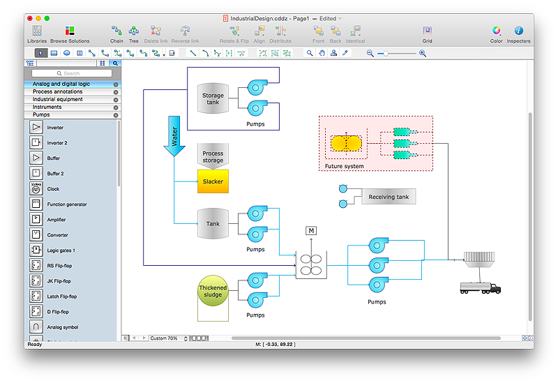
Process Flow Diagram widely used in modeling of processes in the chemical industry. A Chemical Process Flow diagram (PFD) is a specialized type of flowchart. With the help of Chemical Process Flow Diagram engineers can easily specify the general scheme of the processes and chemical plant equipment. Chemical Process Flow Diagram displays the real scheme of the chemical process, the relationship between the equipment and the technical characteristics of the process. Chemical Process Flow Diagram illustrates the connections between the basic equipment as well as the overall structure of pipelines and other supporting equipment. The purpose of the PFD is to build the image of the basic idea of the chemical process. ConceptDraw PRO together with its Chemical and Process Engineering solution delivers the possibility to design Chemical Process Flow diagrams. It is designed for chemical industry engineers and designers."A process flow diagram (PFD) is a diagram commonly used in chemical and process engineering to indicate the general flow of plant processes and equipment. The PFD displays the relationship between major equipment of a plant facility and does not show minor details such as piping details and designations. Another commonly used term for a PFD is a flowsheet. ...
Process flow diagrams of multiple process units within a large industrial plant will usually contain less detail and may be called block flow diagrams or schematic flow diagrams." [Process flow diagram. Wikipedia]
The process flow diagram (PFD) template for the ConceptDraw PRO diagramming and vector drawing software is included in the Chemical and Process Engineering solution from the Engineering area of ConceptDraw Solution Park.
HelpDesk
How to Draw a Process Flow Diagram in ConceptDraw PRO
Process Flow diagrams are used in chemical and process engineering to show the flow of chemicals and the equipment involved in the process. When it comes to creating a process flow diagram, it's important to use software that is capable of describing a wide range of processes, using techniques and graphical notation that are easily recognized by engineering workers. An ideal drawing platform will utilize functions that can cope with the output of a high volume of engineering processes, that may change rapidly from development to implementation stages. ConceptDraw PRO, with the extended functionality of the Chemical and Process Engineering Diagrams solution, is the ideal medium for creating designs of this type. The Chemical and Process Engineering Diagrams solution complements this feature with a library of selected icons to represent various steps — all instantly recognizable and applicable to a wide user base. ConceptDraw PRO allows you to draw the Process Flow diagram easily using the set of special libraries.- Process Flowchart | Basic Flowchart Symbols and Meaning | Flow ...
- Process Flow Chart For Store Department
- Basic Flowchart Symbols and Meaning | Process Flowchart | Flow ...
- Process Flow Diagram Symbols
- How to Draw a Chemical Process Flow Diagram | Chemical and ...
- Data Flow Diagram
- Process Flow Diagram For Account
- Process Flow Diagram Symbols | Process Flowchart | Process Flow ...
- Swim Lane Diagrams | Cross-Functional Flowchart (Swim Lanes ...
- Process Flowchart | How to Draw a Chemical Process Flow Diagram ...
- UML 2 4 Process Flow Diagram | Software Work Flow Process in ...
- Basic Flowchart Symbols and Meaning | Data Flow Diagrams | Visio ...
- Design Of A Flow Chart For A Manufacturing Process
- Process Flowchart | Business process Flow Chart - Event-Driven ...
- Top 5 Android Flow Chart Apps | Army Flow Charts | Process ...
- Process Flowchart | Basic Flowchart Symbols and Meaning ...
- Process Flowchart | Data Flow Diagram Model | Flow chart Example ...
- Process Flow Chart
- Process Flowchart | Technical Flow Chart Example | How to Draw a ...
- Flow chart Example. Warehouse Flowchart | Process Flowchart ...

-template-process-flow-diagram-(pfd)-template.png--diagram-flowchart-example.png)
