 Engineering
This solution extends ConceptDraw DIAGRAM.4 with the ability to visualize industrial systems in electronics, electrical, chemical, process, and mechanical engineering.
HelpDesk
How to Draw a Chemical Process Flow Diagram

HelpDesk
How to Create a Mechanical Diagram

 Chemical and Process Engineering
This chemical engineering solution extends ConceptDraw DIAGRAM.9.5 (or later) with process flow diagram symbols, samples, process diagrams templates and libraries of design elements for creating process and instrumentation diagrams, block flow diagrams (BFD
Process Engineering
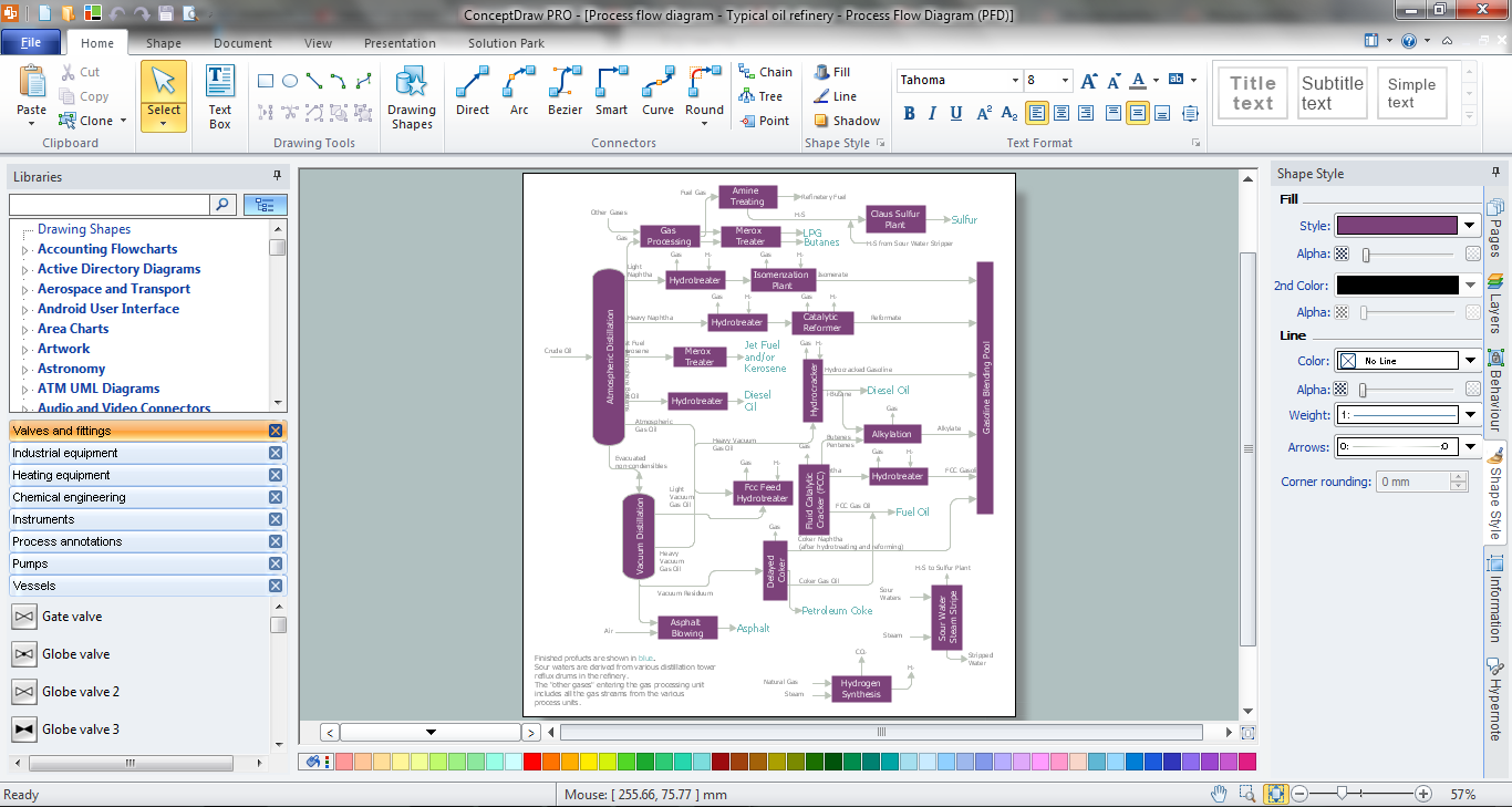
Process Flow Diagram Symbols

 ConceptDraw Solution Park
ConceptDraw Solution Park collects graphic extensions, examples and learning materials
 Mechanical Engineering
This solution extends ConceptDraw DIAGRAM.9 mechanical drawing software (or later) with samples of mechanical drawing symbols, templates and libraries of design elements, for help when drafting mechanical engineering drawings, or parts, assembly, pneumatic,
Technical Drawing Software

Process and Instrumentation Diagram
The vector stencils library "Heating equipment" contains 42 symbols of regenerators, intercoolers, heaters, and condensers.
Use these shapes for drawing cooling systems, heat recovery systems, thermal, heat transfer and mechanical design, and process flow diagrams (PFD).
"Heating or cooling of processes, equipment, or enclosed environments are within the purview of thermal engineering.
One or more of the following disciplines may be involved in solving a particular thermal engineering problem:
Thermodynamics,
Fluid mechanics,
Heat transfer,
Mass transfer.
Thermal engineering may be practiced by mechanical engineers and chemical engineers.
One branch of knowledge used frequently in thermal engineering is that of thermofluids." [Thermal engineering. Wikipedia]
The design elements example "Heating equipment" was created using the ConceptDraw PRO diagramming and vector drawing software extended with the Chemical and Process Engineering solution from the Engineering area of ConceptDraw Solution Park.
Heating equipment symbols

 Cross-Functional Flowcharts
Cross-functional flowcharts are powerful and useful tool for visualizing and analyzing complex business processes which requires involvement of multiple people, teams or even departments. They let clearly represent a sequence of the process steps, the order of operations, relationships between processes and responsible functional units (such as departments or positions).
Process Diagrams
- Engineering Process Flow
- Engineering | How to Draw a Chemical Process Flow Diagram | How ...
- Mechanical Engineering | Process Flow Chart | Technical Drawing ...
- Process Flow Chart | Mechanical Engineering | Chemical and ...
- Mechanical Drawing Symbols | Process Flow Diagram Symbols ...
- Mechanical Engineering | Mechanical Drawing Symbols | Process ...
- Mechanical Drawing Symbols | Mechanical Engineering | Process ...
- How to Draw a Chemical Process Flow Diagram | Workflow Diagram ...
- Process Flow Diagram Assembly
- Mechanical Engineering | Engineering | Chemical and Process ...
- Process Flowchart | How to Draw a Process Flow Diagram in ...
- Process Flowchart | Flow process chart | Flow chart Example ...
- Process Flow Charts Mechanical
- Mechanical Drawing Symbols | Electrical Schematic Symbols ...
- Technical Drawing Software | Mechanical Engineering | Mechanical ...
- Engineering | Technical Drawing Software | Mechanical Engineering ...
- Mechanical Drawing Symbols | Mechanical Engineering | Process ...
- Process Flow Diagram Symbols | Chemical Engineering | Process ...
- Chemical and Process Engineering | Process Flow Diagram ...
- How to Draw a Chemical Process Flow Diagram | Chemical and ...