The vector stencils library "Rack diagrams" contains 33 rack design elements for drawing the computer network server rack diagrams.
"A 19-inch rack is a standardized frame or enclosure for mounting multiple equipment modules. Each module has a front panel that is 19 inches (482.6 mm) wide, including edges or ears that protrude on each side which allow the module to be fastened to the rack frame with screws. ...
Equipment designed to be placed in a rack is typically described as rack-mount, rack-mount instrument, a rack mounted system, a rack mount chassis, subrack, rack mountable, or occasionally simply shelf. The height of the electronic modules is also standardized as multiples of 1.75 inches (44.45 mm) or one rack unit or U (less commonly RU). The industry standard rack cabinet is 42U tall. ...
19-inch racks in 2-post or 4-post form hold most equipment in modern data centers, ISP facilities and professionally designed corporate server rooms. They allow for dense hardware configurations without occupying excessive floorspace or requiring shelving." [19-inch rack. Wikipedia]
The clip art example "Rack diagrams - Vector stencils library" was created using the ConceptDraw PRO diagramming and vector drawing software extended with the Rack Diagrams solution from the Computer and Networks area of ConceptDraw Solution Park.
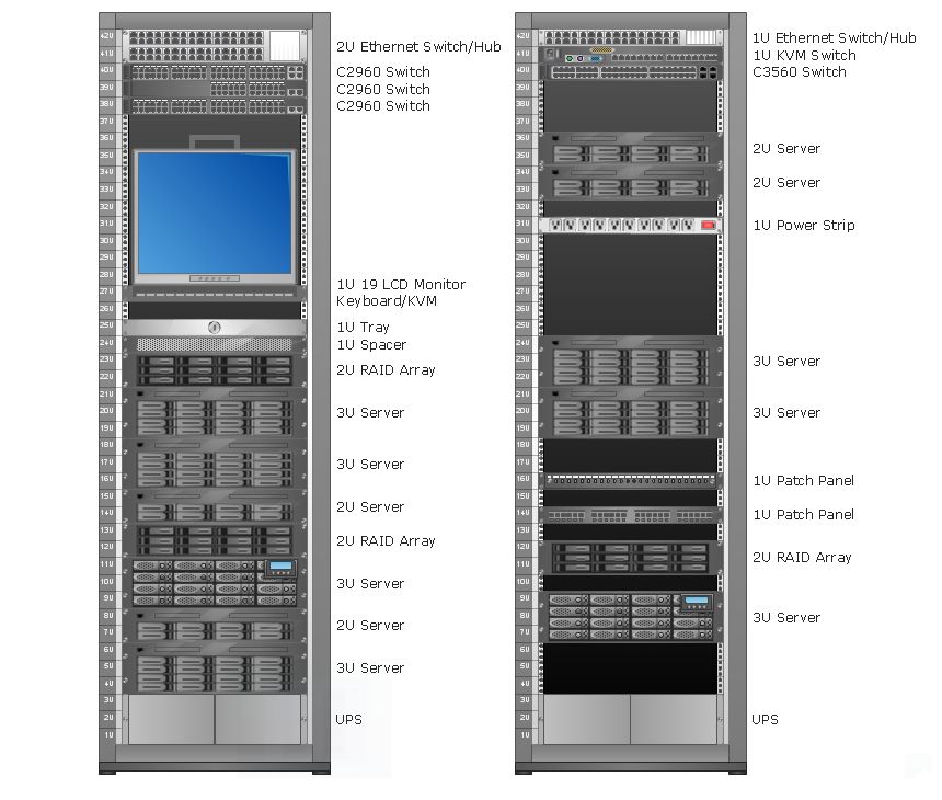
Server rack diagrams visualize the the rack mounting of computer and network equipment as the drawing of frontal view of the rack with equipment installed. They are used for choosing the equipment or racks to buy, and help to organize equipment on the racks virtually, without the real installation.
"A 19-inch rack is a standardized frame or enclosure for mounting multiple equipment modules. Each module has a front panel that is 19 inches (482.6 mm) wide, including edges or ears that protrude on each side which allow the module to be fastened to the rack frame with screws." [19-inch rack. Wikipedia]
"A rack unit, U or RU is a unit of measure that describes the height of equipment designed to mount in a 19-inch rack or a 23-inch rack. The 19-inch (482.6 mm) or 23-inch (584.2 mm) dimension refers to the width of the equipment mounting frame in the rack including the frame; the width of the equipment that can be mounted inside the rack is less. One rack unit is 1.75 inches (4.445 cm) high.
The size of a piece of rack-mounted equipment is frequently described as a number in "U". For example, one rack unit is often referred to as "1U", 2 rack units as "2U" and so on.
A typical full size rack is 42U, which means it holds just over 6 feet of equipment, and a typical "half-height" rack would be 18-22U, or around 3 feet high." [Rack unit. Wikipedia]
The rack diagram template is included in the Rack Diagrams solution from the Computer and Networks area of ConceptDraw Solution Park.
The vector stencils library "Network layout floorplan" contain 34 symbol icons for drawing computer network floor plans, communication equipment layouts, and structured cabling diagrams.
"Structured cabling is building or campus telecommunications cabling infrastructure that consists of a number of standardized smaller elements (hence structured) called subsystems. ...
Structured cabling design and installation is governed by a set of standards that specify wiring data centers, offices, and apartment buildings for data or voice communications using various kinds of cable, most commonly category 5e (CAT-5e), category 6 (CAT-6), and fibre optic cabling and modular connectors. These standards define how to lay the cabling in various topologies in order to meet the needs of the customer, typically using a central patch panel (which is normally 19 inch rack-mounted), from where each modular connection can be used as needed. Each outlet is then patched into a network switch (normally also rack-mounted) for network use or into an IP or PBX (private branch exchange) telephone system patch panel." [Structured cabling. Wikipedia]
The design elements example "Network layout floorplan - Vector stencils library" was created using the ConceptDraw PRO diagramming and vector drawing software extended with the Network Layout Floor Plans solution from the Computer and Networks area of ConceptDraw Solution Park.
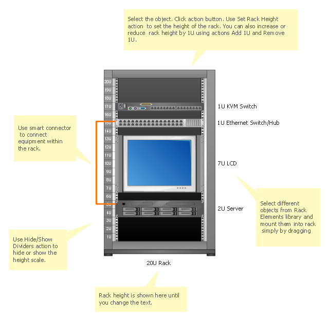
Design Element: Rack Diagram for Network Diagrams
ConceptDraw PRO is perfect for software designers and software developers who need to draw Rack Diagrams.
"An application server can be either a software framework that provides a generalized approach to creating an application-server implementation, without regard to what the application functions are, or the server portion of a specific implementation instance. In either case, the server's function is dedicated to the efficient execution of procedures (programs, routines, scripts) for supporting its applied applications." [Application server. Wikipedia]
"Hardware requirement for servers vary, depending on the server application. Absolute CPU speed is not quite as critical to a server as it is to a desktop machine. Servers' duties to provide service to many users over a network lead to different requirements such as fast network connections and high I/ O throughout. Since servers are usually accessed over a network, they may run in headless mode without a monitor or input device. Processes that are not needed for the server's function are not used. Many servers do not have a graphical user interface (GUI) as it is unnecessary and consumes resources that could be allocated elsewhere. Similarly, audio and USB interfaces may be omitted. ...
As servers need a stable power supply, good Internet access, increased security and are also noisy, it is usual to store them in dedicated server centers or special rooms. This requires reducing the power consumption, as the extra energy used generates more heat thus causing the temperature in the room to exceed acceptable limits; hence normally, server rooms are equipped with air conditioning devices. Server casings are usually flat and wide (typically measured in "rack units"), adapted to store many devices next to each other in a server rack. Unlike ordinary computers, servers usually can be configured, powered up and down or rebooted remotely, using out-of-band management, typically based on IPMI." [Server (computing). Wikipedia]
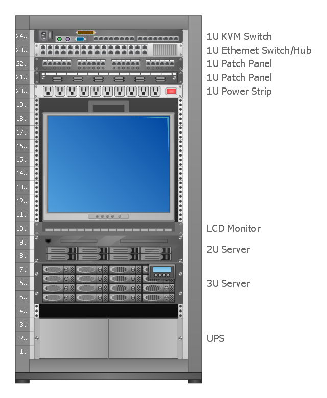
A rack diagram is useful for designing and documenting of network rack server equipment (19-inch or 23-inch rack, rack cabinet, rack unit, network switch, router, KVM switch, server) of data centers, ISP facilities and corporate server rooms.
This application server rack diagram example was created using the ConceptDraw PRO diagramming and vector drawing software extended with the Rack Diagrams solution from the Computer and Networks area of ConceptDraw Solution Park.
HelpDesk
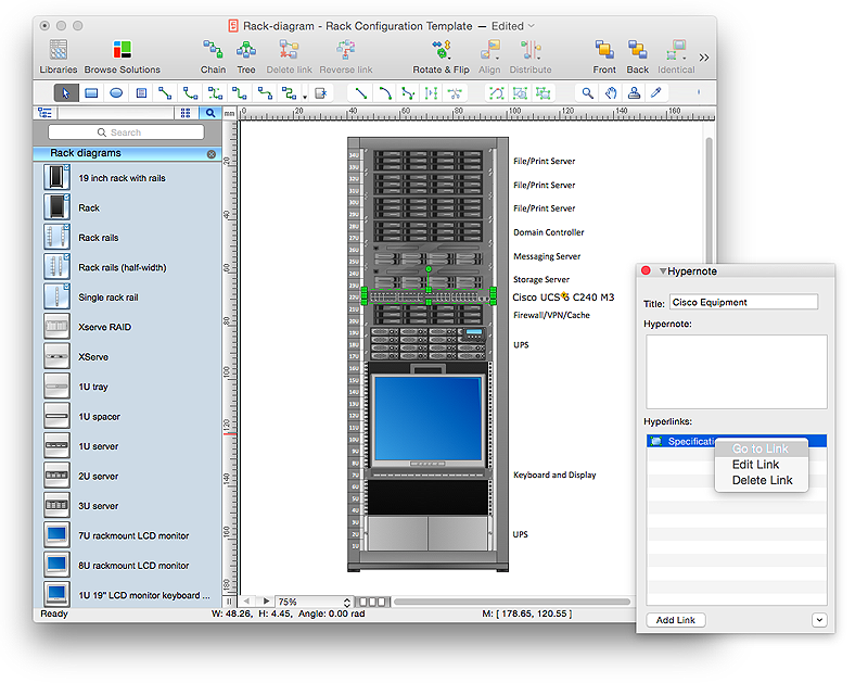
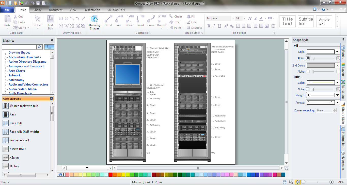
How to Create a Rack Diagram in ConceptDraw PRO
A Rack Diagram represents the rack mounting of network and computer equipment that is installed as a server. Rack diagrams are used by system administrators and network architectors when making a decision regarding the purchase of network equipment. It is used to show how a particular server configuration can be composed, without making its physical installation. ConceptDraw PRO enhanced with the Rack Diagrams Solution can be successfully used for making various rack diagrams. It's important that the solution used to create a rack diagram contains templates that stick to industry standards, and supplies a big selection of device icons to cover multiple types of equipment for a number of network configurations.HelpDesk
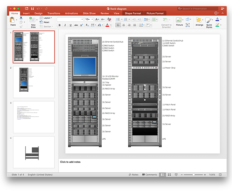
How to Add a Rack Diagram to a PowerPoint Presentation Using ConceptDraw PRO
Rack diagrams are created to make short work of configuring and documenting the server and network equipment of the rack frameworks. Rack diagrams may be useful when considering equipment purchasing, or installing. Using the ConceptDraw Rack Diagrams solution, you can quickly and easily design a rack diagram from the set of vector graphic objects that are fully consistent with accepted industry standards. The Rack diagram will help you when considering and purchasing a rack of network equipment. When installing equipment, a rack diagram will help you to situate equipment quickly and in a due manner. The PowerPoint presentation on concept of your server room rack layouts can be very informative and helpful. ConceptDraw PRO allows you to easily create wireless network diagrams and then make a PowerPoint Presentation from your diagrams in a single click.
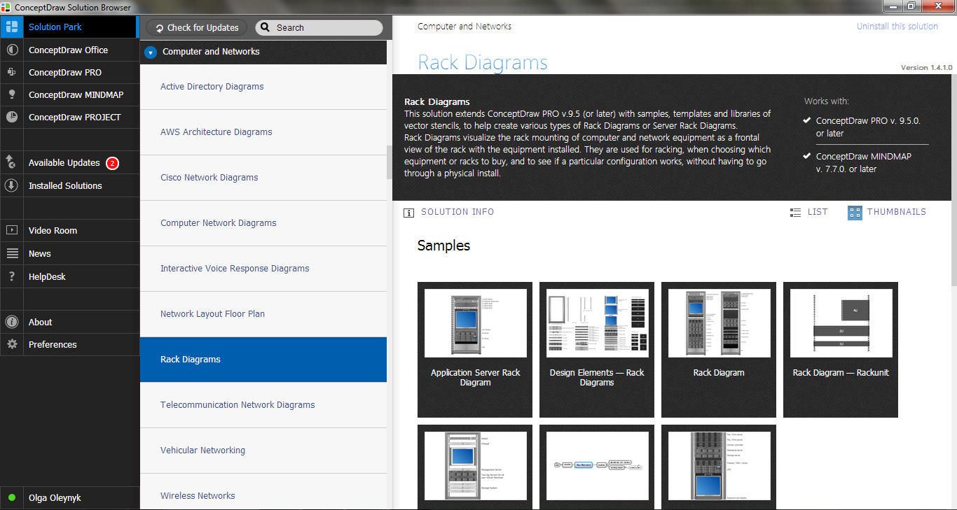
 Rack Diagrams
Rack Diagrams solution extends ConceptDraw PRO software with samples, templates and libraries of vector stencils for drawing the computer network server rack mounting diagrams.
HelpDesk
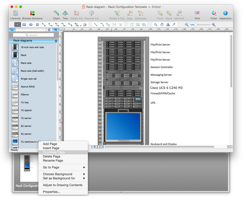
How to Create Multipage Diagram
Most ConceptDraw PRO templates are one page in length. Some templates consist of two pages: the first page — as the main page, and a second page as the background page. You can customize any template for your needs by adding pages, rearranging them, or by setting a custom background.Rack Solutions
Rack Solutions are very helpful and now widely used by specialists for drawing the rack diagrams, for visualization of rack mounting of computer and network equipment. ConceptDraw PRO diagramming and vector drawing software also keeps up to the times and offers a powerful Rack Diagrams Solution from the Computer and Networks Area.The Rack
The Rack Diagrams represent the frontal view of the rack with network equipment installed. They are helpful and widely used for choosing the equipment and racks to buy, and give the possibility to visually plan how to organize it on the racks. Now creating of the Rack Diagrams is quite simple and quick thanks to the powerful drawing tools of the Rack Diagrams Solution from the Computer and Networks Area.HelpDesk
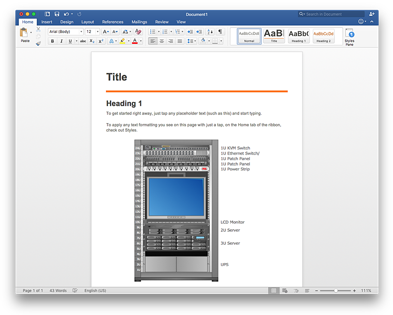
How to Add a Rack Diagram to a MS Word Document Using ConceptDraw PRO
Rack Diagram depicts the structure of network equipment installation, and provides network administrator with the base to support electronic equipment, power, cooling, and cable management. ConceptDraw PRO allows you to easily create diagram that will help to detail the type of rack equipment that best fits your needs and then lets you to insert the scheme of rack configuration into the network documentation pack. ConceptDraw PRO allows you to easily create rack configuration diagrams and then insert them into a MS Word document.Rack Diagrams
Rack Diagrams visualize the rack mounting of computer and network equipment as the drawing of frontal view of the rack with equipment installed. They are used for choosing the equipment or racks to buy, and help to organize equipment on the racks virtually, without the real installation.
Network Diagramming Software for Design Rack Diagrams
Rack Diagrams visualize the rack mounting of computer and network equipment as the drawing of frontal view of the rack with equipment installed. They are used for choosing the equipment or racks to buy, and help to organize equipment on the racks virtually, without the real installation. Network Diagramming Software - ConceptDraw PRO is perfect for software designers and software developers who need to draw Rack Diagrams.
- 19 Rack Panel Dimensions
- U Rack Panel Number Cabinet Frame
- Server Rack 19 With Equipment
- Rack diagrams - Vector stencils library | How To Create Restaurant ...
- Rack diagrams - Vector stencils library | Network Diagramming ...
- Rack diagrams - Vector stencils library | Network Icons | 1u 24 Port ...
- Ofc Patch Panel
- Panel Over Server Rack
- Rack Mount Patch Panel Visio Stencil
- Rack diagrams - Vector stencils library | Patch Panel 24 Port Svg
- Rack Server 19 Inch
- Patch Panel Stencil Visio
- Rack diagram - Template | How To use Switches in Network ...
- 19 Inch Computer Rack
- Rack diagrams - Vector stencils library
- 1u Fiber Patch Panel Visio Stencil
- Fiber Patch Panel Visio Stencil
- Fiber Panel Front View
- Rack diagrams - Vector stencils library | Design Element: Rack ...


-rack-diagrams---vector-stencils-library.png--diagram-flowchart-example.png)


-rack-diagrams---vector-stencils-library.png--diagram-flowchart-example.png)
-rack-diagrams---vector-stencils-library.png--diagram-flowchart-example.png)
-rack-diagrams---vector-stencils-library.png--diagram-flowchart-example.png)
-rack-diagrams---vector-stencils-library.png--diagram-flowchart-example.png)
-rack-diagrams---vector-stencils-library.png--diagram-flowchart-example.png)
-rack-diagrams---vector-stencils-library.png--diagram-flowchart-example.png)


-rack-diagrams---vector-stencils-library.png--diagram-flowchart-example.png)
-rack-diagrams---vector-stencils-library.png--diagram-flowchart-example.png)
-rack-diagrams---vector-stencils-library.png--diagram-flowchart-example.png)




.png)
_Win_Mac.png)