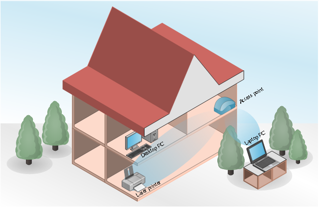
This wireless network diagram sample depicts home area network (HAN).
"One of the most common ways of creating a home network is by using wireless radio signal technology; the 802.11 network as certified by the IEEE. Most products that are wireless-capable operate at a frequency of 2.4 GHz under 802.11b and 802.11g or 5 GHz under 802.11a. Some home networking devices operate in both radio-band signals and fall within the standard 802.11n.
A wireless network can be used for communication between many electronic devices, to connect to the Internet or to wired networks that use Ethernet technology. Wi-Fi is a marketing and compliance certification for IEEE 802.11 technologies. The WiFi Alliance has tested compliant products certifies them for interoperability." [Home network. Wikipedia]
The HAN diagram example "Home wireless network" was created using the ConceptDraw PRO diagramming and vector drawing software extended with the Wireless Networks solution from the Computer and Networks area of ConceptDraw Solution Park.
Electrical Symbols — VHF UHF SHF
Ultra high frequency (UHF) is the ITU designation for radio frequencies in the range between 300 MHz and 3 GHz, also known as the decimetre band as the wavelengths range from one meter to one decimetre. Radio waves with frequencies above the UHF band fall into the SHF (super-high frequency) or microwave frequency range. Lower frequency signals fall into the VHF (very high frequency) or lower bands. UHF radio waves propagate mainly by line of sight; they are blocked by hills and large buildings although the transmission through building walls is strong enough for indoor reception. They are used for television broadcasting, cell phones, satellite communication including GPS, personal radio services including Wi-Fi and Bluetooth, walkie-talkies, cordless phones, and numerous other applications. 26 libraries of the Electrical Engineering Solution of ConceptDraw PRO make your electrical diagramming simple, efficient, and effective. You can simply and quickly drop the ready-to-use objects from libraries into your document to create the electrical diagram.Electrical Symbols, Electrical Diagram Symbols
When drawing Electrical Schematics, Electrical Circuit Diagrams, Power Systems Diagrams, Circuit and Wiring Diagrams, Digital and Analog Logic Schemes, you will obligatory need the electrical symbols and pictograms to represent various electrical and electronic devices, such as resistors, wires, transistors, inductors, batteries, switches, lamps, readouts, amplifiers, repeaters, relays, transmission paths, semiconductors, generators, and many more. Today these symbols are internationally standardized, so the diagrams designed using them are recognizable and comprehensible by specialists from different countries. Electrical Engineering Solution included to ConceptDraw Solution Park provides 26 libraries with 926 commonly used electrical schematic and electrical engineering symbols making the reality the easy drawing of Electrical diagrams, schematics and blueprints. Now you need only a few minutes to create great-looking Electrical diagram, simply choose required electrical design elements from the libraries, drag them on the needed places at the document and connect in a suitable way.Electrical Drawing Software and Electrical Symbols
Any electrical device could not be created without electrical diagram, wiring also cannot be laid without pre-designed and approved scheme or plan. Electrical drawing is a type of technical drawing that depicts scheme of some electrical device and includes the information about power, lighting, etc. Electrical plan designed for architectural or engineering project visually displays location of electrical devices and connections. ConceptDraw PRO is ideal electrical software for construction professional-looking Electrical Circuits, Electrical Schematics, Electrical Layouts, Electrical Wiring, Automotive Wiring, Cabling Layout Diagrams, Circuits and Logic Schematics, Logic Gate Diagrams, Digital Circuits, Parallel Circuits, Blue Prints with help of 926 standard electrical symbols offered by 26 libraries of Electrical Engineering solution from the Engineering area for ConceptDraw PRO. It makes drawing Electrical diagrams very easy even for beginners, and also extends your work with various export methods.
 Telecommunication Network Diagrams
Telecommunication Network Diagrams solution extends ConceptDraw PRO software with samples, templates, and great collection of vector stencils to help the specialists in a field of networks and telecommunications, as well as other users to create Computer systems networking and Telecommunication network diagrams for various fields, to organize the work of call centers, to design the GPRS networks and GPS navigational systems, mobile, satellite and hybrid communication networks, to construct the mobile TV networks and wireless broadband networks.
Electrical Engineering
Electrical engineering is a field of engineering that generally deals with the study and application of electricity, electronics, and electromagnetism. ConceptDraw PRO extended with Electrical Engineering Solution from the Industrial Engineering Area of ConceptDraw Solution Park is the best Electrical Engineering software. You have an excellent possibility to make sure this right now.Mesh Network Topology Diagram
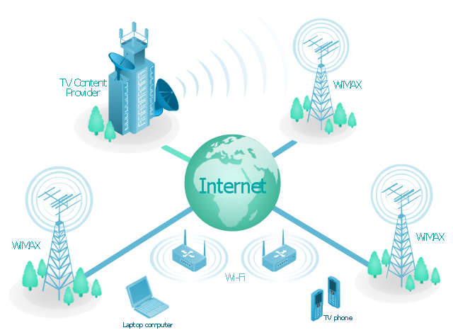
A Mesh Network Topology is a computer network topology built on the principle of cells. The network workstations are the mesh nodes, they are connected to each other, usually to the principle "each with each" (a fully connected network) and interact in the distribution of data in a network. Each node relays the data for the network and can take the role of switch for other participants. Mesh Network Topology is sufficiently complex to configure, but however it provides a high fault tolerance, has a capability for self-healing and is considered as quite reliable. Large number of nodes' connections assures a wide selection of route of following the traffic within a network, therefore the breaking of one connection will not disrupt the functioning of network as a whole. As a rule, the Mesh Networks are wireless. The Mesh Network Topology Diagrams of any complexity and Wireless Mesh Network Diagrams are easy for construction in ConceptDraw PRO diagramming and vector drawing software using the tools of Computer Network Diagrams solution from Computer and Networks area."Mobile IPTV is a technology that enables users to transmit and receive multimedia traffic including television signal, video, audio, text and graphic services through IP-based the wired and wireless networks with support for Quality of Service/ QoE, security, mobility, and interactive functions. Through Mobile IPTV, users can enjoy IPTV services anywhere and even while on the move." [Mobile IPTV. Wikipedia]
This mobile web-based TV network diagram example was created using the ConceptDraw PRO diagramming and vector drawing software extended with the Telecommunication Network Diagrams solution from the Computer and Networks area of ConceptDraw Solution Park.
This mobile web-based TV network diagram example was created using the ConceptDraw PRO diagramming and vector drawing software extended with the Telecommunication Network Diagrams solution from the Computer and Networks area of ConceptDraw Solution Park.
The vector stencils library "Computers and network isometric" contains 56 3D clipart images of computer and network devices and equipment for drawing network diagrams.
The clip art example "Computers and network isometric - Vector stencils library" was created using the ConceptDraw PRO diagramming and vector drawing software extended with the Computer and Networks solution from the Computer and Networks area of ConceptDraw Solution Park.
The clip art example "Computers and network isometric - Vector stencils library" was created using the ConceptDraw PRO diagramming and vector drawing software extended with the Computer and Networks solution from the Computer and Networks area of ConceptDraw Solution Park.
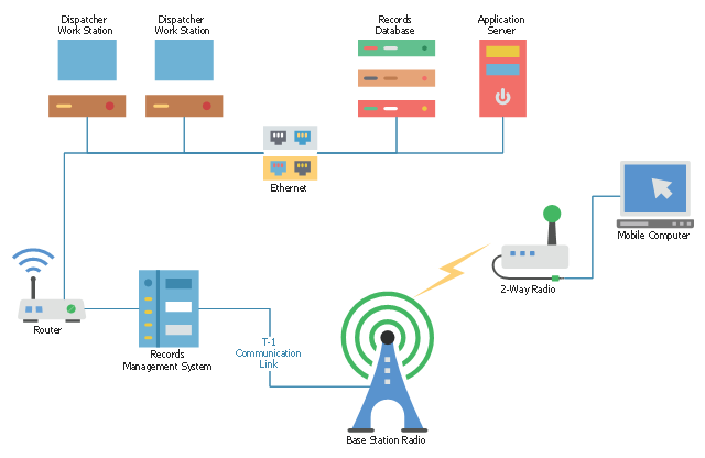
This telecommunication diagram sample shows the Mobile 2-Way Radio Network. It was designed on the base of the Diagram – Mobile 2-Way Radio Network from the "Telecommunications Handbook for Transportation Professionals: The Basics of Telecommunications" on the website of the Office of Operations of the Federal Highway Administration, the U.S. Department of Transportation.
"Mobile 2-Way Radio
Generally used between vehicles for wide area communication in a Private Land Mobile Radio Service (PLMRS) on frequencies set aside by the Federal Communications Commission (FCC) for that purpose. The system is used by DOT maintenance groups to facilitate operations between work crews and a central (or regional) dispatch center. Under the definition of the National Architecture, this is a wide-area mobile communication system. These same systems can also be used to coordinate joint operations between Police Departments and the DOT. These systems can also provide for an exchange of digital data information."
[ops.fhwa.dot.gov/ publications/ telecomm_ handbook/ chapter3.htm]
The telecom diagram example "Mobile 2-way radio network" was created using the ConceptDraw PRO diagramming and vector drawing software extended with the Computers and Communications solution from the Illustration area of ConceptDraw Solution Park.
- Wireless access point - Network diagram | Hotel Network Topology ...
- Give Out The Drawing Of Television And Radio Diagrams
- Radio Signal Png
- Home wireless network diagram
- Radio Canopy
- Fishbone diagram - HAN project | Home wireless network diagram ...
- Home wireless network diagram | Wireless Networks | Network ...
- Telecommunication networks. Computer and Network Examples ...
- Wireless router network diagram | What Is a Wireless Network ...
- Wireless access point - Network diagram | Cisco - Vector stencils ...


