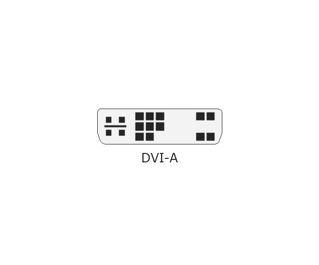
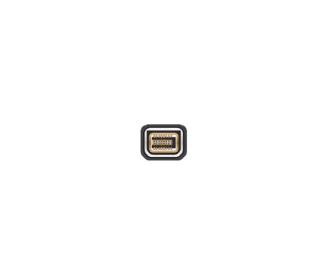
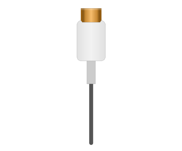
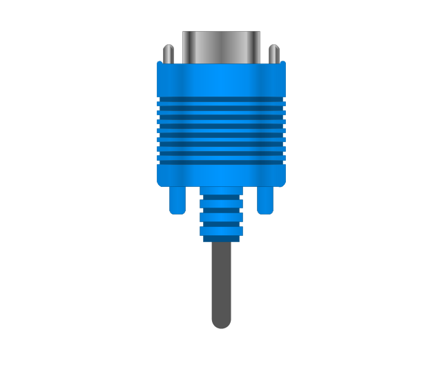
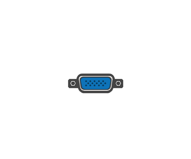
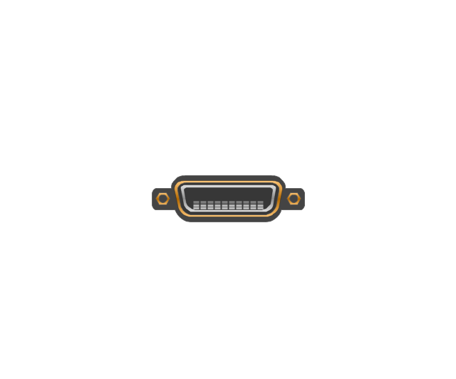
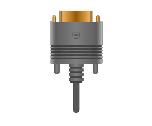
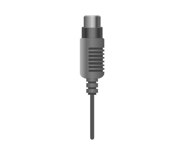
Standard Universal Audio & Video Connection Types
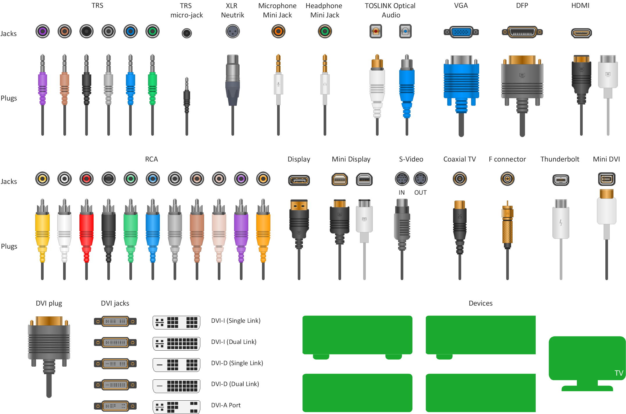
The Audio & Video Connectors solution contains a set of pre-designed objects, libraries, templates, and samples; allowing quick and easy diagramming of various configurations of audio and video devices.Audio Visual Connectors Types
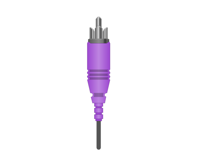
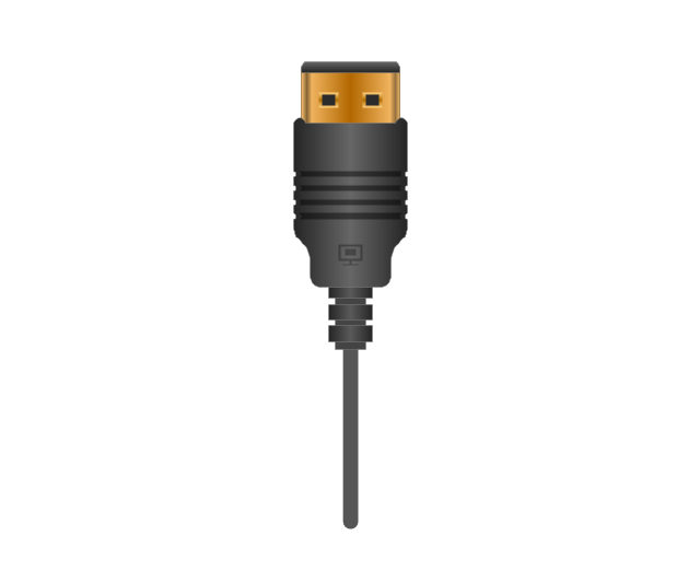
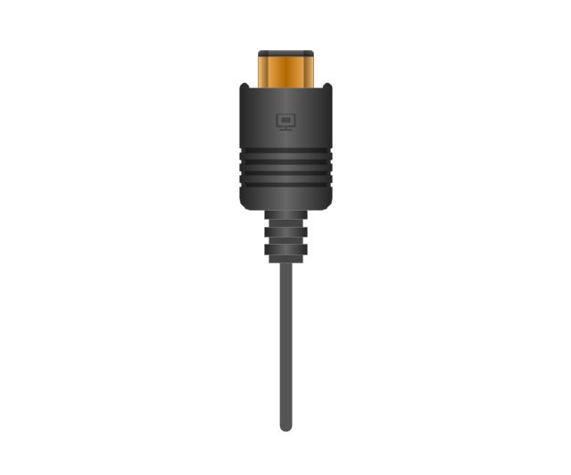
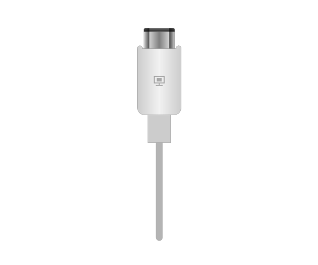
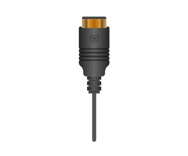
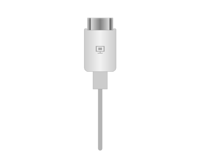
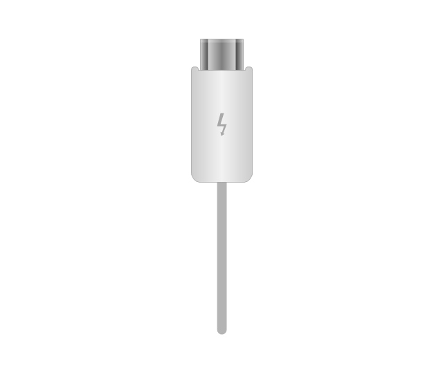
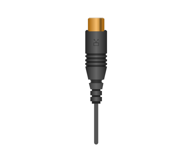
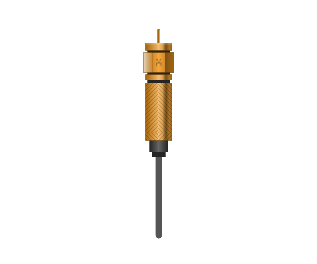
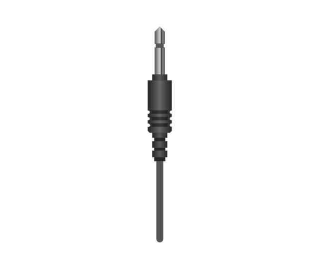
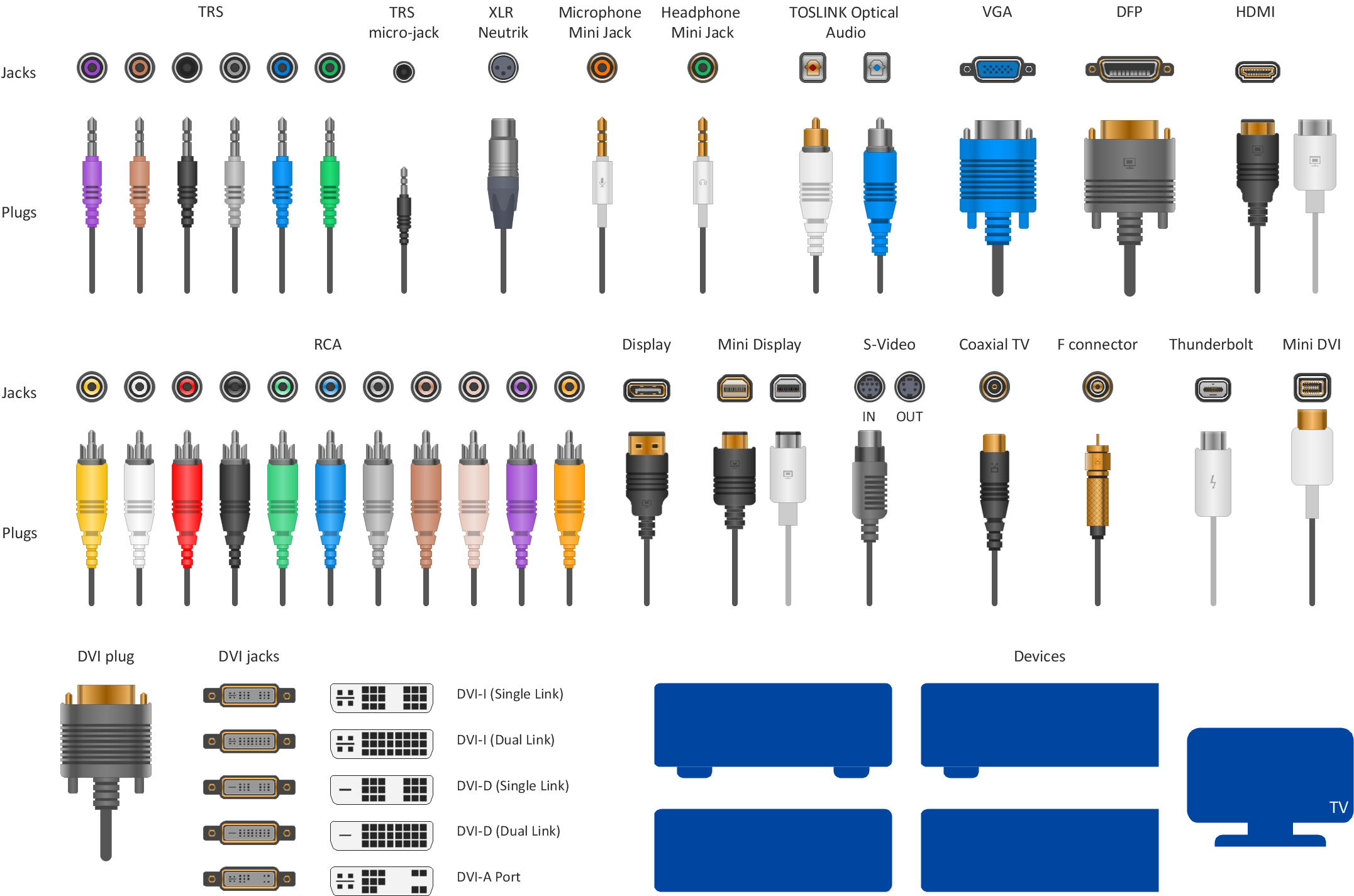
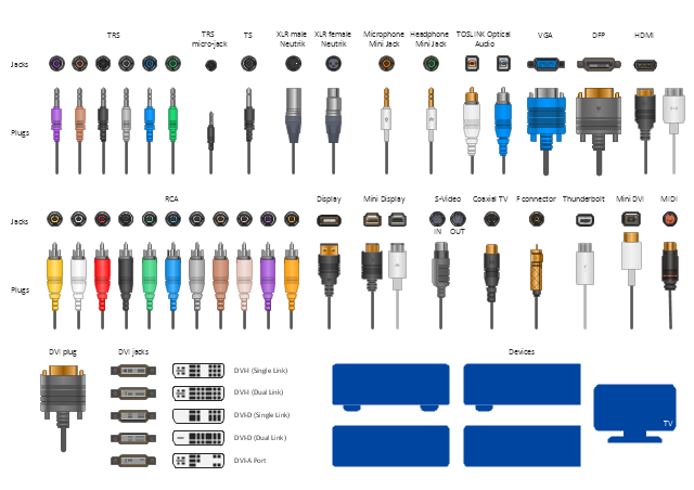
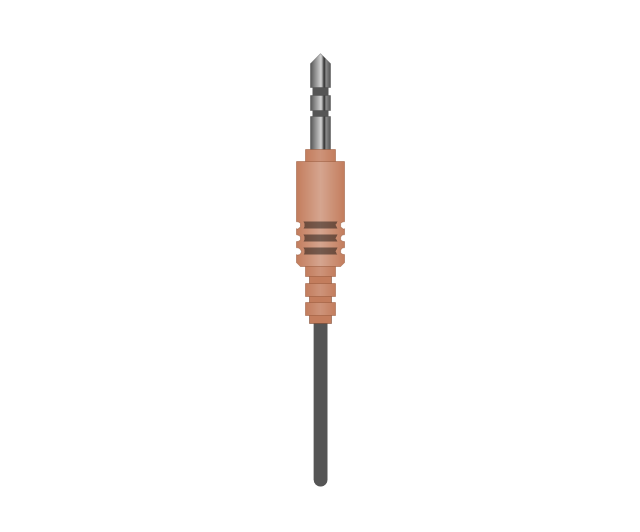
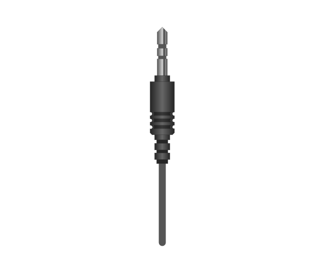
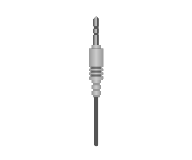
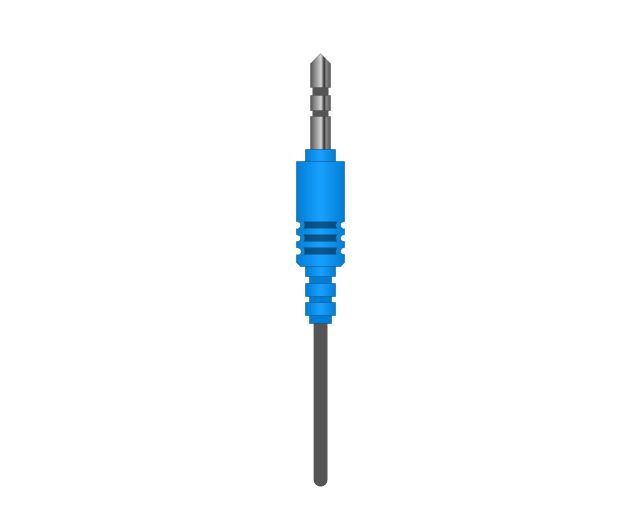
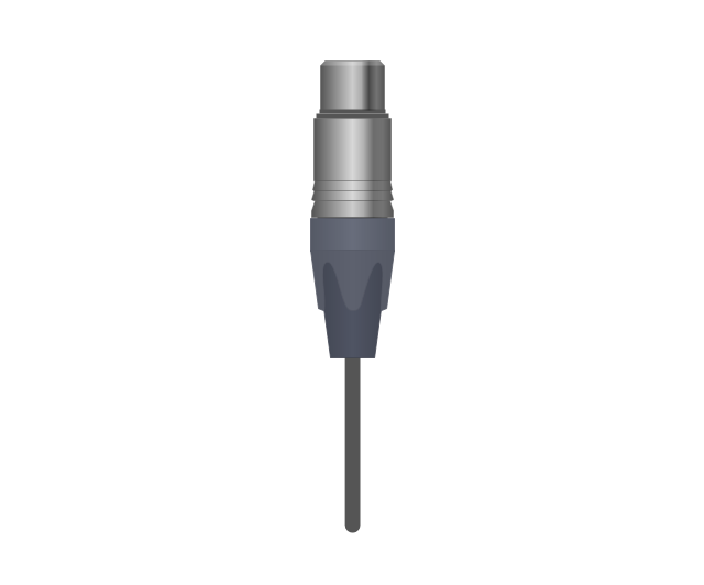
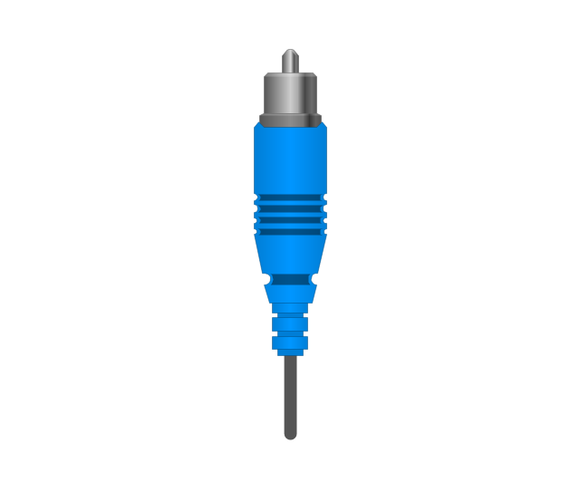
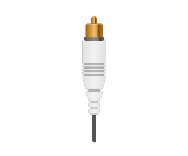
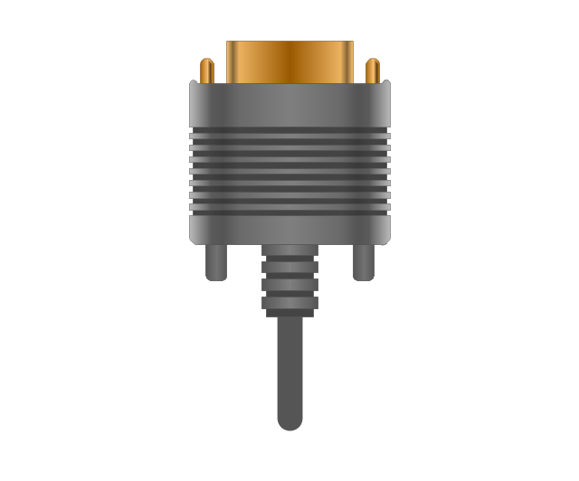
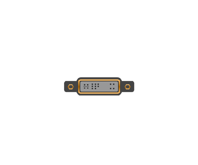
The Audio & Video Connectors solution contains a set of pre-designed objects, libraries, templates, and samples; allowing quick and easy diagramming of various configurations of audio and video devices.The vector stencils library "Audio and video connectors" contains 94 symbols of audio and video connectors (TRS, TS, XLR, microphone, headphone, TOSLINK, DVI, VGA, DFP, S-Video, RCA, display port, HDMI, Thunderbolt, coaxial TV, F connector, MIDI) and device silhouettes.
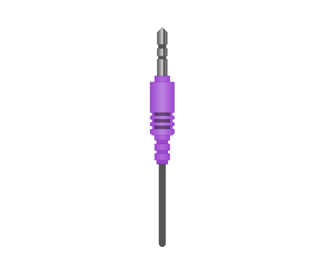
Use these jacks and plugs clipart icons for drawing hook up diagrams.
"Audio connectors and video connectors are electrical connectors (or optical connectors) for carrying audio signal and video signal, of either analog or digital format. Analog A/ V connectors often use shielded cables to inhibit radio frequency interference (RFI) and noise." [Audio and video connector. Wikipedia]
"The existence of many different audio and video standards necessitates the definition of hardware interfaces, which define the physical characteristics of the connections between electrical equipment. This includes the types and numbers of wires required along with the strength and frequency of the signal. It also includes the physical design of the plugs and sockets.
An interface may define a connector that is used only by that interface (e.g., DVI) or may define a connector that is also used by another interface; for example, RCA connectors are defined both by the composite video and component video interfaces.
Audio connectors and video connectors are electrical connectors (or optical connectors) for carrying audio signal and video signal, of either analog or digital format. Analog A/ V connectors often use shielded cables to inhibit radio frequency interference (RFI) and noise.
Since both analog and digital signals are used with some styles of connectors, knowledge of the interface used is necessary for a successful transfer of signals. Some interface types use only a distinctive connector or family of connectors, to ensure compatibility. Especially with analog interfaces, physically interchangeable connectors may not carry compatible signals.
Some of these connectors, and other types of connectors, are also used at radio frequency (RF) to connect a radio or television receiver to an antenna or to a cable system..." [Audio and video interfaces and connectors. Wikipedia]
The clipart icons example "Design elements - Audio and video connectors" was created using the ConceptDraw PRO diagramming and vector drawing software extended with the Audio and Video Connectors solution from the Engineering area of ConceptDraw Solution Park.
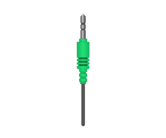
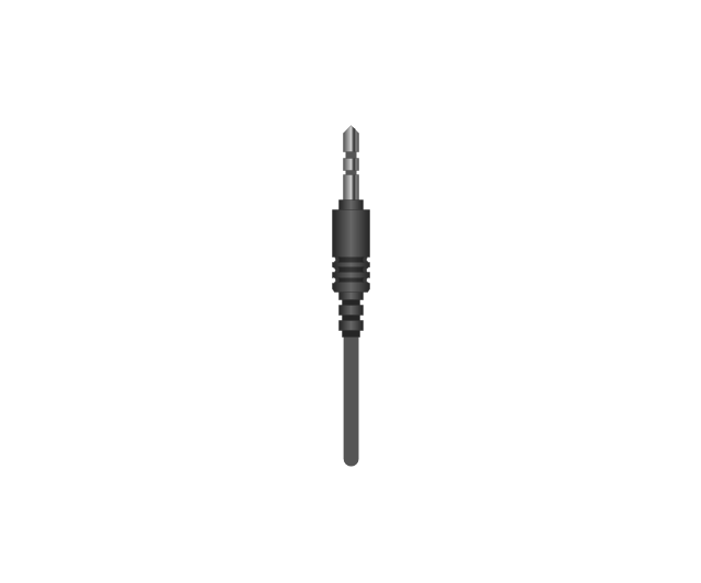
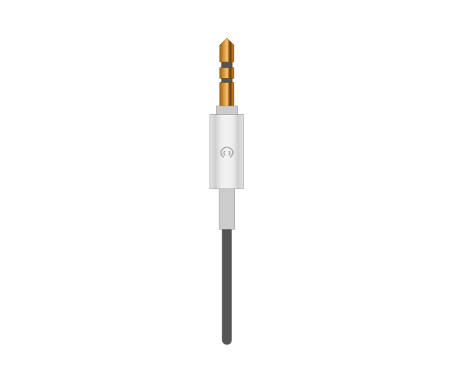
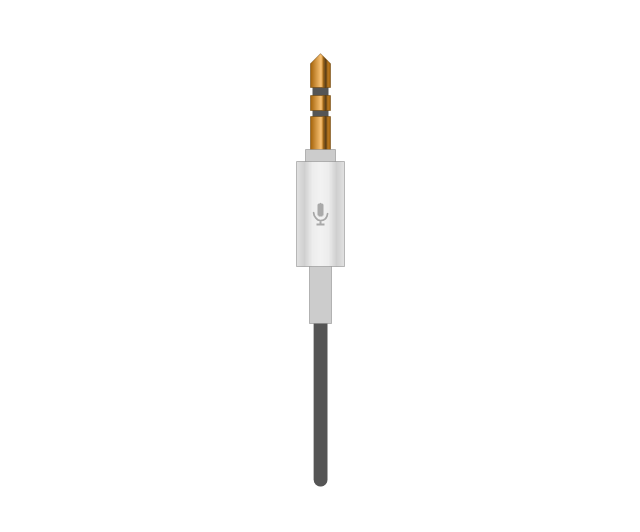
The vector stencils library "Audio and video connectors" contains 94 symbols of audio and video connectors and device silhouettes.
Use these jacks and plugs clipart icons for drawing hook up diagrams in the ConceptDraw PRO diagramming and vector drawing software extended with the Audio and Video Connectors solution from the Engineering area of ConceptDraw Solution Park.
www.conceptdraw.com/ solution-park/ engineering-audio-video-connectors
HelpDesk
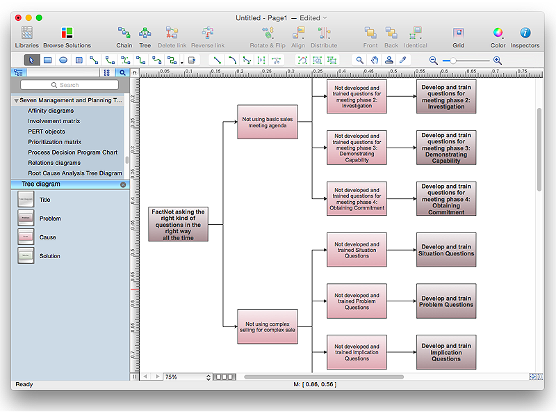
How To Create Root Cause Analysis Diagram Using ConceptDraw Office
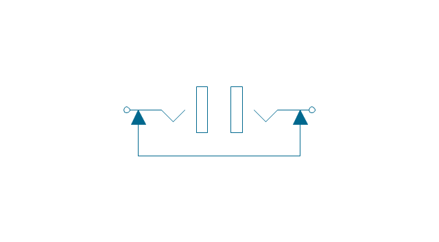
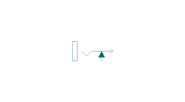
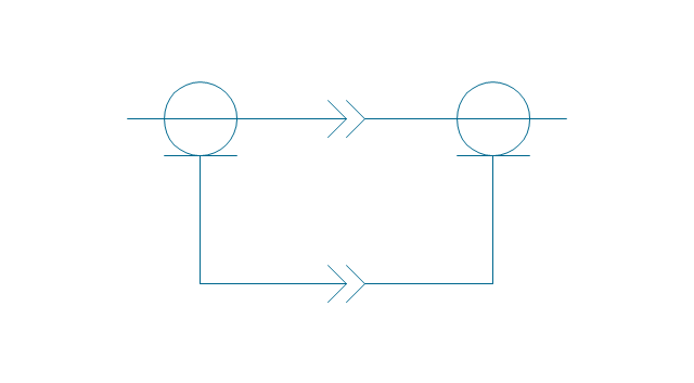
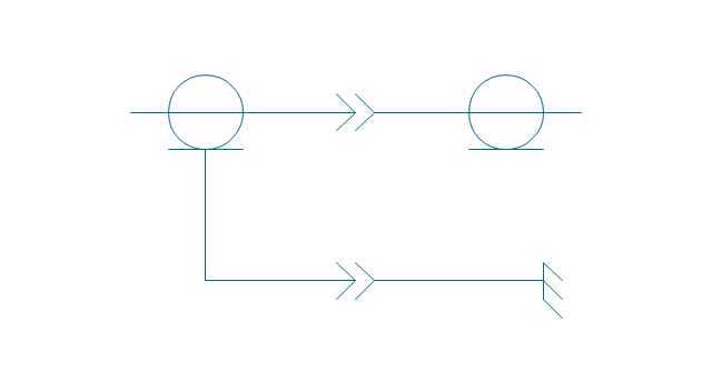
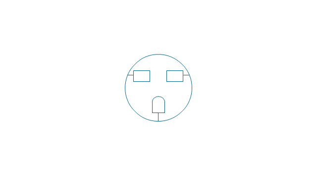
Root Cause Analysis (RCA) is used to determine the main causes of the problem. If the certain factor is the root cause, this mean that its vanishing will help to prevent the further recurrence of the problem. Root Cause Analysis diagram is used to analyze the root causes of factors that influence the problem. It helps to identify the root causes for a factor and then propose possible corrective actions. A diagram is constructed separately for each high priority factor. The ability to create a RCA tree diagram from a mind map is supported by the ConceptDraw Seven Management and Planning Tools solution.The vector stencils library "Terminals and connectors" contains 43 element symbols of terminals, connectors, plugs, polarized connectors, jacks, coaxial cables, and conductors.
Use it for drawing the wiring diagrams, electrical layouts, electronic schematics, and circuit diagrams in the ConceptDraw PRO diagramming and vector drawing software extended with the Electrical Engineering solution from the Engineering area of ConceptDraw Solution Park.
www.conceptdraw.com/ solution-park/ engineering-electrical
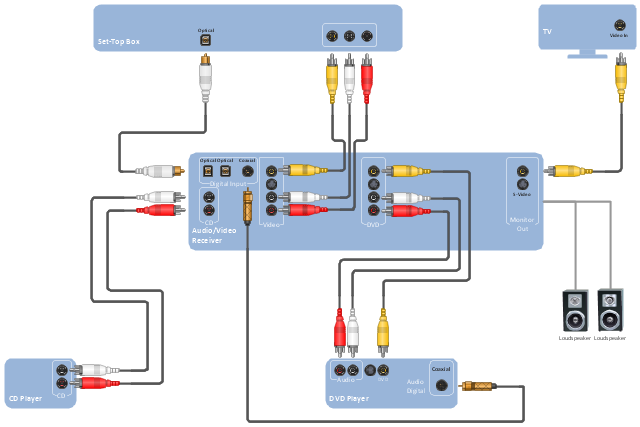
"Home cinema, also commonly called home theater or home theatre, refers to home entertainment systems that seek to reproduce a movie theater experience and mood, with the help of video and audio equipment in or outside a private home." [Home cinema. Wikipedia]
The hookup drawing example "Hook up diagram - Stereo audio/ visual entertainment system" was created using the ConceptDraw PRO diagramming and vector drawing software extended with the Audio and Video Connectors solution from the Engineering area of ConceptDraw Solution Park.
The hookup drawing example "Hook up diagram - Stereo audio/ visual entertainment system" was created using the ConceptDraw PRO diagramming and vector drawing software extended with the Audio and Video Connectors solution from the Engineering area of ConceptDraw Solution Park.
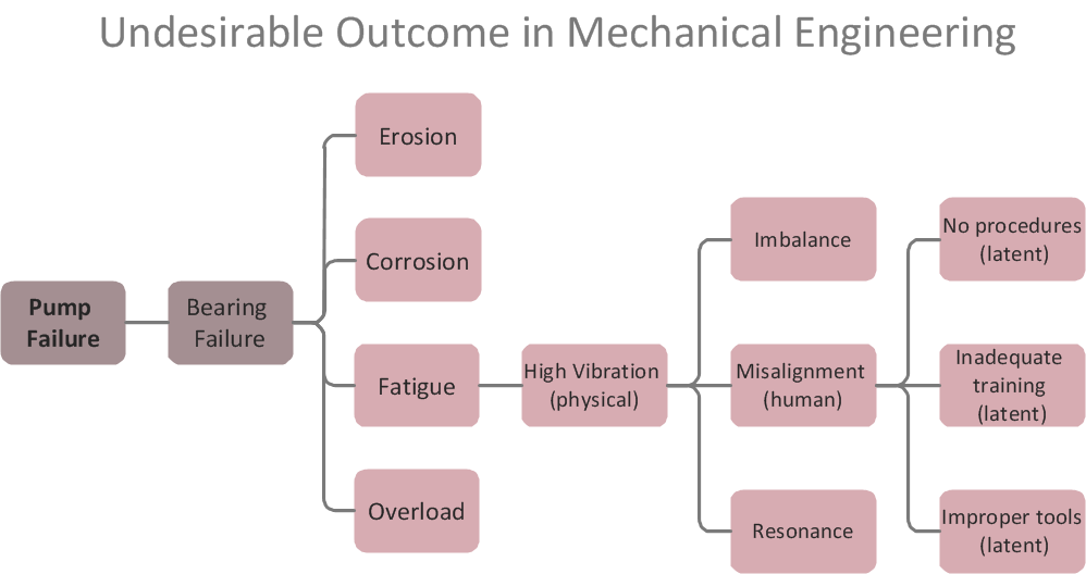
PROBLEM ANALYSIS. Root Cause Analysis Tree Diagram
Root Cause Analysis Tree Diagram. Use the Root Cause Diagram to perform visual root cause analysis. Root Cause Analysis Tree Diagram is constructed separately for each highly prioritized factor. The goal of this is to find the root causes for the factor and list possible corrective action. ConceptDraw Office suite is a software for problem analysis.
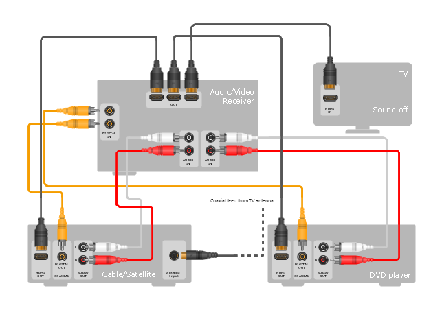
"Surround sound is a technique for enriching the sound reproduction quality of an audio source with additional audio channels from speakers that surround the listener (surround channels), providing sound from a 360° radius in the horizontal plane (2D) as opposed to "screen channels" (centre, [front] left, and [front] right) originating only from the listener's forward arc.
Surround sound is characterized by a listener location or sweet spot where the audio effects work best, and presents a fixed or forward perspective of the sound field to the listener at this location. The technique enhances the perception of sound spatialization by exploiting sound localization; a listener's ability to identify the location or origin of a detected sound in direction and distance. Typically this is achieved by using multiple discrete audio channels routed to an array of loudspeakers.
There are various surround sound based formats and techniques, varying in reproduction and recording methods along with the number and positioning of additional channels." [Surround sound. Wikipedia]
The hookup diagram example "Hook up drawing - Home entertainment system with surround sound" was created using the ConceptDraw PRO diagramming and vector drawing software extended with the Audio and Video Connectors solution from the Engineering area of ConceptDraw Solution Park.
- Design elements - Audio and video connectors | Vdeo Rca Male ...
- Rca Jack To Dvi Pinout Diagram
- Standard Universal Audio & Video Connection Types | Vga To Rca ...
- Rca Cable Diagram
- Rca Connector Phono Diagram
- Rca Connector Diagram Wire
- Vga Pin 15 D Sub To Rca Jack Wiring Diagram Step By Step
- Audio Video Jack Internal Diagram
- Audio Jack Cables Diagram For Drawing
- Rca Connector Female Diagram
- Diagram Jack Rca
- Standard Universal Audio & Video Connection Types | Audio Visual ...
- Standard Universal Audio & Video Connection Types | Xlr To Stereo ...
- Design elements - Audio and video connectors
- DVI pinout diagram | Standard Universal Audio & Video Connection ...
- Audio and video connectors - Vector stencils library | Standard ...
- Audio and Video Connectors
- Standard Universal Audio & Video Connection Types | Audio and ...
- Rca Connector Wiring Diagram














-jack-audio-and-video-connectors---vector-stencils-library.png--diagram-flowchart-example.png)
-jack-audio-and-video-connectors---vector-stencils-library.png--diagram-flowchart-example.png)
-jack-audio-and-video-connectors---vector-stencils-library.png--diagram-flowchart-example.png)
-jack-audio-and-video-connectors---vector-stencils-library.png--diagram-flowchart-example.png)
-audio-and-video-connectors---vector-stencils-library.png--diagram-flowchart-example.png)
-audio-and-video-connectors---vector-stencils-library.png--diagram-flowchart-example.png)
-audio-and-video-connectors---vector-stencils-library.png--diagram-flowchart-example.png)
-audio-and-video-connectors---vector-stencils-library.png--diagram-flowchart-example.png)
