Jacobson Use Cases Diagram
The vector stencils library UML Use Case contains specific symbols of the UML notation such as actors, actions, associations and relationships for the ConceptDraw PRO diagramming and vector drawing software. This library is contained in the Rapid UML solution from Software Development area of ConceptDraw Solution Park.This SysML diagram example was redesigned from Wikimedia Commons file: Use case restaurant model.svg.
"Use case model of a restaurant business." [commons.wikimedia.org/ wiki/ File:Use_ case_ restaurant_ model.svg]
"The use case diagram describes the usage of a system (subject) by its actors (environment) to achieve a goal, that is
realized by the subject providing a set of services to selected actors. The use case can also be viewed as functionality and/
or capabilities that are accomplished through the interaction between the subject and its actors. Use case diagrams include the use case and actors and the associated communications between them. Actors represent classifier roles that are external to the system that may correspond to users, systems, and or other environmental entities. They may interact either directly or indirectly with the system. The actors are often specialized to represent a taxonomy of user types or external systems." [omg.org/ spec/ SysML/ 1.3/ ]
The SysML diagram example "Use case restaurant model" was drawn using the ConceptDraw PRO diagramming and vector drawing software extended with the SysML solution from the Software Development area of ConceptDraw Solution Park.
 SYSML
SYSML
The SysML solution helps to present diagrams using Systems Modeling Language; a perfect tool for system engineering.
Model Based Systems Engineering
ConceptDraw PRO is a professional diagramming and vector drawing software. Now, enhanced with SysML Solution from the Software Development Area of ConceptDraw Solution Park, ConceptDraw PRO became an ideal software for model based systems engineering (MBSE).Use Case Diagrams technology with ConceptDraw PRO
Use case diagrams are used at the development of software and systems for definition of functional system requirements or system of systems. Use case diagram presents the consecution of object’s actions (user’s or system’s) which are executed for reaching the definite result.UML Use Case Diagram. Design Elements
UML Use Case Diagrams are used to illustrate the structure of arbitrarily complex systems and illustrates the service consumer - service provider relationship between components.
Financial Trade UML Use Case Diagram Example
This sample represents the actors, use cases and dependencies between them, and also the relationships between use cases. There are used dependency and use case generalization associations on this UML diagram. Use case generalization is used when you have two similar use cases, but one of them does more than another. This sample shows the work of the Financial Trade sphere and can be used by trading companies, commercial organizations, traders, different exchanges.UML Use Case Diagram Example. Services UML Diagram. ATM system
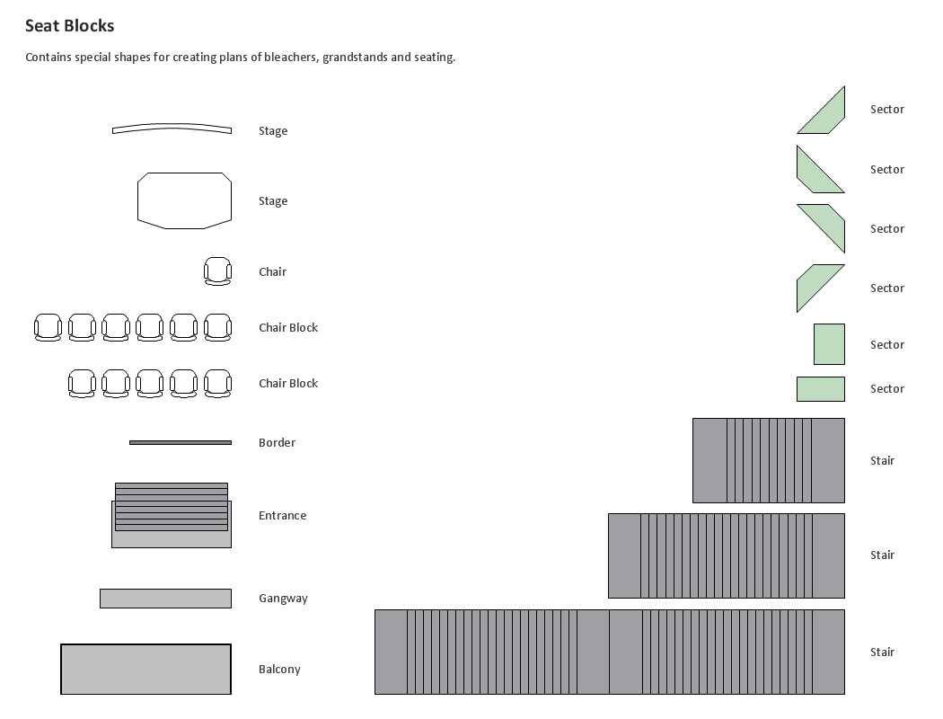
Services UML Diagram. ATM system. This sample was created in ConceptDraw PRO diagramming and vector drawing software using the UML Use Case Diagram library of the Rapid UML Solution from the Software Development area of ConceptDraw Solution Park. This sample shows the scheme of the servicing using the ATMs (Automated Teller Machines) and is used at the working of ATM banking systems, at the performing of the banking transactions.Building Drawing Design Element: Seat Blocks
Professional building designs for creating unique looks, such as bleachers, grandstands and seating and more.
Systems Engineering
Systems engineering is an interdisciplinary field of engineering that focuses on how to design and manage complex engineering systems over their life cycles. ConceptDraw PRO supplied with SysML Solution from the Software Development Area of ConceptDraw Solution Park is a powerful and effective systems engineering software.UML Class Diagram Generalization Example UML Diagrams
This sample was created in ConceptDraw PRO diagramming and vector drawing software using the UML Class Diagram library of the Rapid UML Solution from the Software Development area of ConceptDraw Solution Park. This sample describes the use of the classes, the generalization associations between them, the multiplicity of associations and constraints. Provided UML diagram is one of the examples set that are part of Rapid UML solution.Create Sophisticated Professional Diagrams - Simply
ConceptDraw PRO is a powerful software that helps you create professional and easy drawing diagrams for business, technology, science and education.
 ATM UML Diagrams
The ATM UML Diagrams solution lets you create ATM solutions and UML examples. Use ConceptDraw PRO as a UML diagram creator to visualize a banking system.
Flowchart Examples
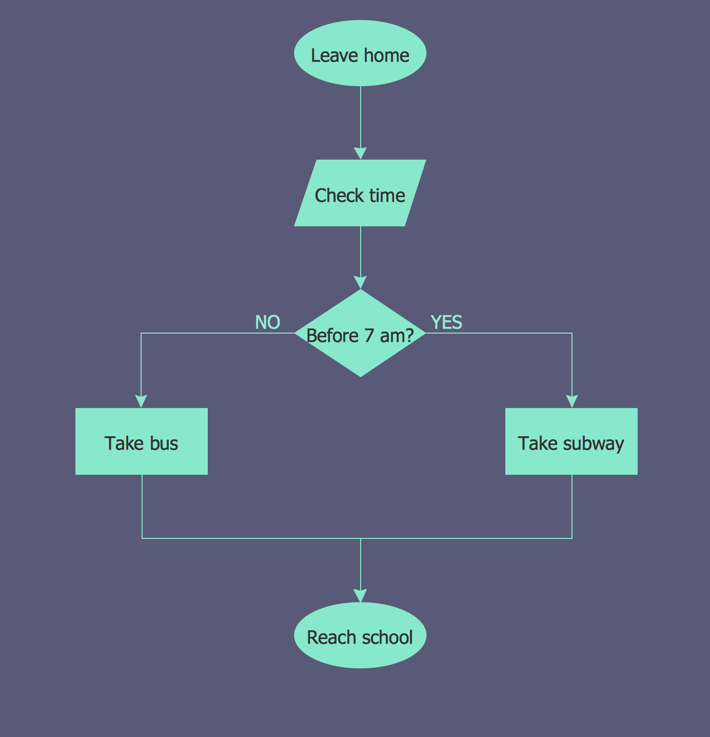
It’s very simple, convenient and quick to design professional looking Flowcharts of any complexity using the ConceptDraw PRO diagramming and vector drawing software extended with Flowcharts Solution from the "What is a Diagram" Area of ConceptDraw Solution Park which provides a wide set of predesigned objects, templates, samples and Flowchart examples.Event-Driven Process Chain Diagram Software
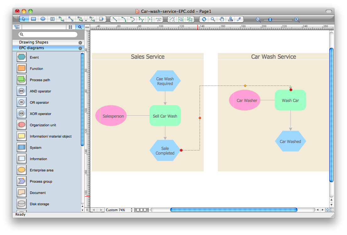
It’s very easy, quick and convenient to draw the Event-driven Process Chain (EPC) diagrams in ConceptDraw PRO diagramming and vector drawing software using the Event-driven Process Chain Diagrams Solution from the Business Processes area of ConceptDraw Solution Park.- Usecase Diagram For Restaurant System
- Restaurant For Use Case Diagram And Data Flow Diagram
- Jacobson Use Cases Diagram | Use case restaurant model | UML ...
- Jacobson Use Cases Diagram | Use case restaurant model | Use ...
- Use Case Diagram For A Restaurant System
- Use Case Diagram For Restaurant Automation System
- Jacobson Use Cases Diagram | UML Use Case Diagram Example ...
- Use case restaurant model | Jacobson Use Cases Diagram ...
- Use Case Diagram Restaurant Management System
- Use Case Diagrams Restaurant Management System Actors
- SYSML | Systems Engineering | UML Use Case Diagram Example ...
- Uml Diagrams For Restaurant Management System
- Jacobson Use Cases Diagram | Use case restaurant model | UML ...
- UML Use Case Diagram Example. Services UML Diagram . ATM ...
- Use Case Structure Structure For Online Restaurant System
- Use Case Diagram Of Restaurant Management
- Dfd Diagram For Restaurant Management System In Software
- SYSML | Systems Engineering | UML Use Case Diagram Example ...
- Use Case Diagram For Restaurant Software


