How To use Switches in Network Diagram


The vector stencils library "Network layout floorplan" contain 34 symbol icons for drawing computer network floor plans and communication equipment and cabling layouts.
"Networking hardware may also be known as network equipment or computer networking devices. Units which are the last receiver or generate data are called hosts or data terminal equipment.
All these terms refer to devices facilitating the use of a computer network. Specifically, they mediate data in a computer network. ...
Typically, networking hardware includes gateways, routers, network bridges, switches, hubs, and repeaters. But it also includes hybrid network devices such as multilayer switches, protocol converters, bridge routers, proxy servers, firewalls, network address translators, multiplexers, network interface controllers, wireless network interface controllers, modems, ISDN terminal adapters, line drivers, wireless access points, networking cables and other related hardware.
The most common kind of networking hardware today is a copper-based Ethernet adapter because of its standard inclusion on most modern computer systems. Wireless networking has, however, become increasingly popular, especially for portable and handheld devices.
Other hardware prevalent in computer networking includes data center equipment (such as file servers, database servers and storage areas), network services (such as DNS, DHCP, email, etc.) as well as devices which assure content delivery." [Networking hardware. Wikipedia]
The shapes example "Design elements - Network layout floorplan" was created using the ConceptDraw PRO diagramming and vector drawing software extended with the Network Layout Floor Plans solution from the Computer and Networks area of ConceptDraw Solution Park.
Network layout floor plan symbols

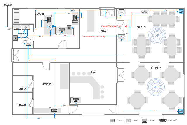
This computer network layout floorplan was drawn on the base of the picture from the Media Institute blog of the Madison Media Institute.
[mediainstitute.edu/ media-schools-blog/ wp-content/ uploads/ 2012/ 01/ floor_ plan.png]
The example "Restaurant network layout floorplan" was created using the ConceptDraw PRO diagramming and vector drawing software extended with the Network Layout Floor Plans solution from the Computer and Networks area of ConceptDraw Solution Park.
Computer network layout floorplan
Network Diagram Software. LAN Network Diagrams. Physical Office Network Diagrams

"In computer networks, networked computing devices pass data to each other along data connections. The connections (network links) between nodes are established using either cable media or wireless media. ...
Network computer devices that originate, route and terminate the data are called network nodes. Nodes can include hosts such as personal computers, phones, servers as well as networking hardware. ...
Network links.
The communication media used to link devices to form a computer network include electrical cable (HomePNA, power line communication, G.hn), optical fiber (fiber-optic communication), and radio waves (wireless networking). In the OSI model, these are defined at layers 1 and 2 - the physical layer and the data link layer.
A widely adopted family of communication media used in local area network (LAN) technology is collectively known as Ethernet. The media and protocol standards that enable communication between networked devices over Ethernet are defined by IEEE 802.3. Ethernet transmit data over both copper and fiber cables. Wireless LAN standards (e.g. those defined by IEEE 802.11) use radio waves, or others use infrared signals as a transmission medium. Power line communication uses a building's power cabling to transmit data. ...
Network nodes.
Apart from the physical communications media described above, networks comprise additional basic system building blocks, such as network interface controller (NICs), repeaters, hubs, bridges, switches, routers, modems, and firewalls." [Computer network. Wikipedia]
The network equipment and cabling layout floorplan template for the ConceptDraw PRO diagramming and vector drawing software is included in the Network Layout Floor Plans solution from the Computer and Networks area of ConceptDraw Solution Park.
LAN equipment and cabling layout floorplan template

Network Gateway Router

Network Printer

Hotel Network Topology Diagram. Hotel Guesthouse WiFi Network

Local area network (LAN). Computer and Network Examples
 diagram")
Network Hubs

This computer network layout floorplan was drawn on the base of the picture from the Media Institute blog of the Madison Media Institute.
[mediainstitute.edu/ media-schools-blog/ wp-content/ uploads/ 2012/ 01/ floor_ plan.png]
The example "Restaurant network layout floorplan" was created using the ConceptDraw PRO diagramming and vector drawing software extended with the Network Layout Floor Plans solution from the Computer and Networks area of ConceptDraw Solution Park.
[mediainstitute.edu/ media-schools-blog/ wp-content/ uploads/ 2012/ 01/ floor_ plan.png]
The example "Restaurant network layout floorplan" was created using the ConceptDraw PRO diagramming and vector drawing software extended with the Network Layout Floor Plans solution from the Computer and Networks area of ConceptDraw Solution Park.
Computer network layout floorplan
Virtual networks. Computer and Network Examples

Star Network Topology


Cisco Routers. Cisco icons, shapes, stencils and symbols

The vector stencils library "Network layout floorplan" contain 34 symbol icons for drawing computer network floor plans, communication equipment layouts, and structured cabling diagrams.
"Structured cabling is building or campus telecommunications cabling infrastructure that consists of a number of standardized smaller elements (hence structured) called subsystems. ...
Structured cabling design and installation is governed by a set of standards that specify wiring data centers, offices, and apartment buildings for data or voice communications using various kinds of cable, most commonly category 5e (CAT-5e), category 6 (CAT-6), and fibre optic cabling and modular connectors. These standards define how to lay the cabling in various topologies in order to meet the needs of the customer, typically using a central patch panel (which is normally 19 inch rack-mounted), from where each modular connection can be used as needed. Each outlet is then patched into a network switch (normally also rack-mounted) for network use or into an IP or PBX (private branch exchange) telephone system patch panel." [Structured cabling. Wikipedia]
The design elements example "Network layout floorplan - Vector stencils library" was created using the ConceptDraw PRO diagramming and vector drawing software extended with the Network Layout Floor Plans solution from the Computer and Networks area of ConceptDraw Solution Park.
PC

Scanner

Switch

Router

Modem

Hub

Rack Mount

Printer

Floor Mounted Outlet

Single Outlet

Duplex Outlet

Direct bus cable

Tops or bottoms bus cable

Side to side bus cable

Multi-tree bus cable

Bottom to side bus cable

Sides bus cable

Door

Door, threshold

Door, stop

Door, stop, threshold

Door, frame

Door, frame, threshold

Door, frame, stop

Door, frame, stop, threshold

Window

Window, sill

Window, sash

Window, sash, sill

Window, frame

Window, frame, sill

Window, frame, sash

Window, frame, sash, sill

- Network Layout Floor Plans | Design elements - Network layout ...
- Floor Plan With Computer Networks
- How To use Switches in Network Diagram | Computer network ...
- How To use Switches in Network Diagram | Communication network ...
- Computer Layout Network With A Switch
- Phisical Layout Firewall Proxy Router Switch Pc Internet
- Network Layout Of Computer With Hub
- Network hardware - Vector stencils library | How To use Switches in ...
- Design elements - Network layout floorplan | Network layout ...
- 10 Computers 1 Router 2 Switches Network Layout
- Router Switch And A Server In A Rack Diagram
- Network Layout Floor Plans | Computer Network Architecture ...
- Cisco Network Templates | Network Diagram Template | Computer ...
- Network Gateway Router | Network Diagramming Software for ...
- Network Layout Floor Plans | Local area network (LAN). Computer ...
- Design elements - Network layout floorplan | Network diagrams with ...
- Network Diagram Software Logical Network Diagram | Network ...
- Network Layout Server Router Switch
- How To use Switches in Network Diagram | Network Diagramming ...