Design Element: Basic Network for Network Diagrams
ConceptDraw PRO is perfect for software designers and software developers who need to draw Basic Network Diagrams.
Design Element: Rack Diagram for Network Diagrams
ConceptDraw PRO is perfect for software designers and software developers who need to draw Rack Diagrams.
Garrett IA Diagrams with ConceptDraw PRO
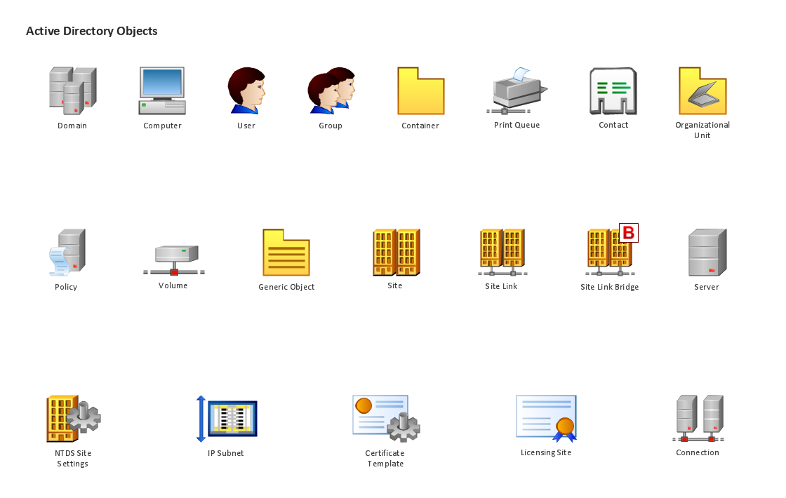
Garrett IA diagrams are used at development of Internet-resources, in particulars at projecting of interactions of web-resource elements. The diagram of information architecture of the web resource which is constructed correctly with necessary details presents to developers the resource in comprehensible and visual way.Design Element: Active Directory for Network Diagrams
ConceptDraw PRO is perfect for software designers and software developers who need to draw Active Directory Network Diagrams.
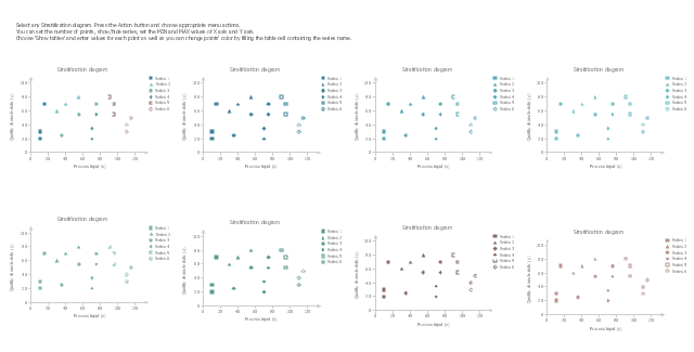
The vector stencils library "Stratification diagram" contains 8 multiseries scatterplot templates.
Use it to design your stratification diagrams with ConceptDraw PRO diagramming and vector drawing software.
"In statistics, stratified sampling is a method of sampling from a population.
In statistical surveys, when subpopulations within an overall population vary, it is advantageous to sample each subpopulation (stratum) independently. Stratification is the process of dividing members of the population into homogeneous subgroups before sampling. The strata should be mutually exclusive: every element in the population must be assigned to only one stratum. The strata should also be collectively exhaustive: no population element can be excluded. Then simple random sampling or systematic sampling is applied within each stratum. This often improves the representativeness of the sample by reducing sampling error. It can produce a weighted mean that has less variability than the arithmetic mean of a simple random sample of the population." [Stratified sampling. Wikipedia]
The stratification is one of the Seven Basic Tools of Quality. [Seven Basic Tools of Quality. Wikipedia]
The example of multiseries scatterplot templates "Design elements - Stratification diagram" is included in the Seven Basic Tools of Quality solution from the Quality area of ConceptDraw Solution Park.
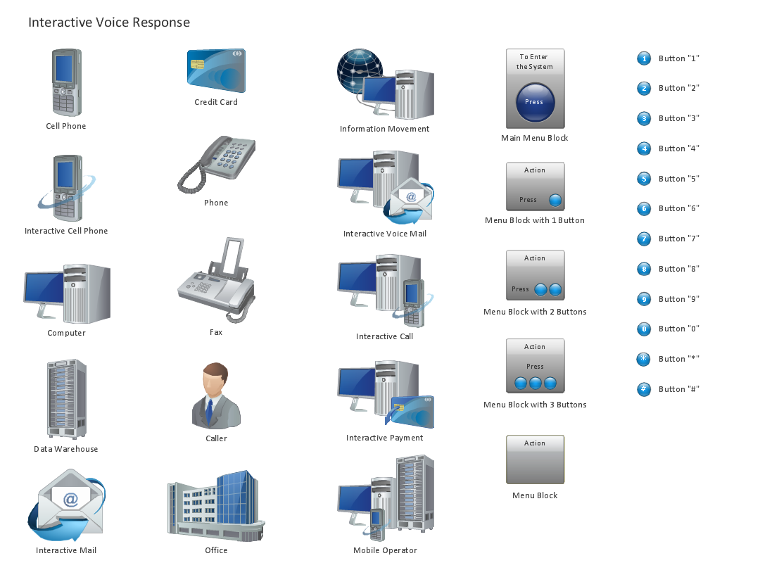
Design Element: IVR for Network Diagrams
ConceptDraw PRO is perfect for software designers and software developers who need to draw IVR Network Diagrams.
Design Element: Network Layout for Network Diagrams
ConceptDraw PRO is perfect for software designers and software developers who need to draw Network Layout Diagrams.
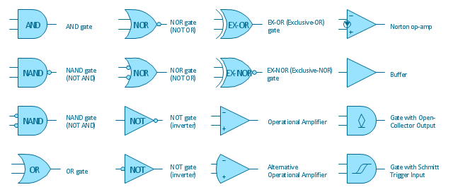
The vector stencils library "Logic gate diagram" contains 17 element symbols for drawing the logic gate diagrams.
"To build a functionally complete logic system, relays, valves (vacuum tubes), or transistors can be used. The simplest family of logic gates using bipolar transistors is called resistor-transistor logic (RTL). Unlike simple diode logic gates (which do not have a gain element), RTL gates can be cascaded indefinitely to produce more complex logic functions. RTL gates were used in early integrated circuits. For higher speed and better density, the resistors used in RTL were replaced by diodes resulting in diode-transistor logic (DTL). Transistor-transistor logic (TTL) then supplanted DTL. As integrated circuits became more complex, bipolar transistors were replaced with smaller field-effect transistors (MOSFETs); see PMOS and NMOS. To reduce power consumption still further, most contemporary chip implementations of digital systems now use CMOS logic. CMOS uses complementary (both n-channel and p-channel) MOSFET devices to achieve a high speed with low power dissipation." [Logic gate. Wikipedia]
The symbols example "Design elements - Logic gate diagram" was drawn using the ConceptDraw PRO diagramming and vector drawing software extended with the Electrical Engineering solution from the Engineering area of ConceptDraw Solution Park.
- Basic Network Diagram | Design Element : Basic Network for ...
- Design Element : Basic Network for Network Diagrams | Design ...
- Design Element : Basic Network for Network Diagrams | Network ...
- How to Draw a Computer Network Diagrams | Design Element ...
- Design Element : Basic Network for Network Diagrams | Network ...
- Business - Design Elements | Advertising - Design Elements ...
- The Building Blocks Used in EPC Diagrams | Building Drawing ...
- Design Element : Basic Network for Network Diagrams ...
- Draw Block Digram Of Element Of Computer
- Basic Network Diagram | ConceptDraw PRO Network Diagram Tool ...
- Network Diagramming Software for Design Computer and Network ...
- Swim Lane Diagrams | Cross-Functional Flowchart (Swim Lanes ...
- Design Element : Basic Network for Network Diagrams | Network ...
- Interior Design Office Layout Plan Design Element | Building ...
- Design Element : Rack Diagram for Network Diagrams | Rack ...
- AWS Simple Icons for Architecture Diagrams | AWS icons 2.0 ...
- Cabinet Design Software | Design Element : Rack Diagram for ...
- Network Diagramming Software for Design Basic Network Diagrams ...
- Design elements - Analog and digital logic | Engineering | Simple ...
.png)
.png)


.png)
