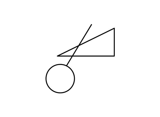
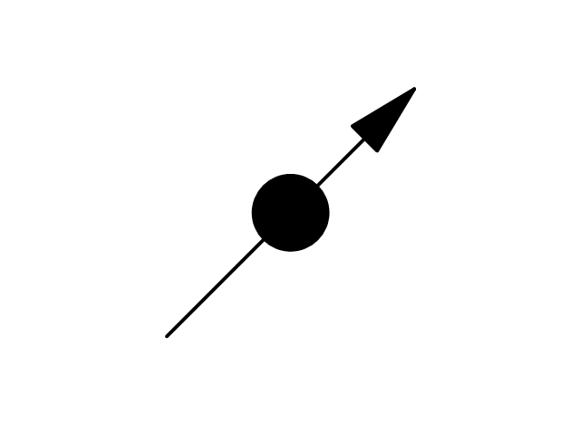
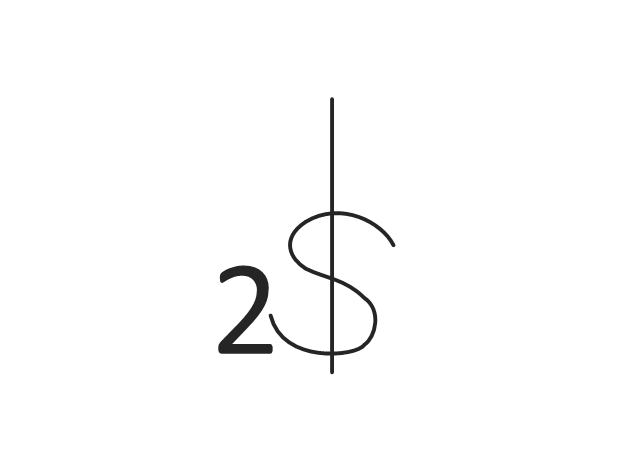
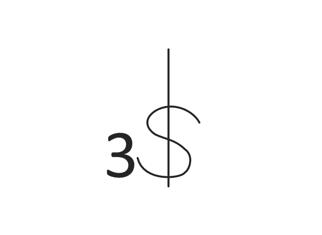
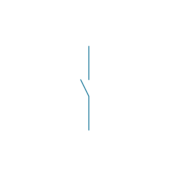
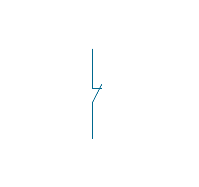
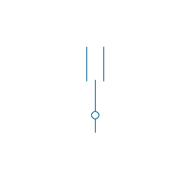
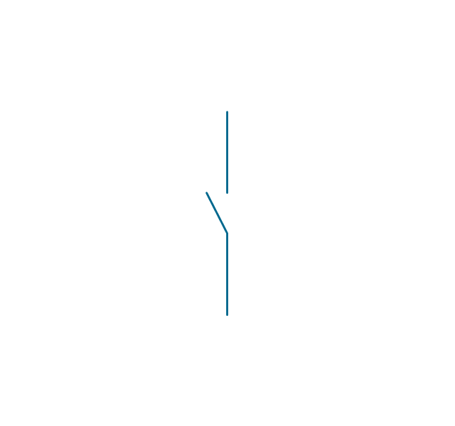
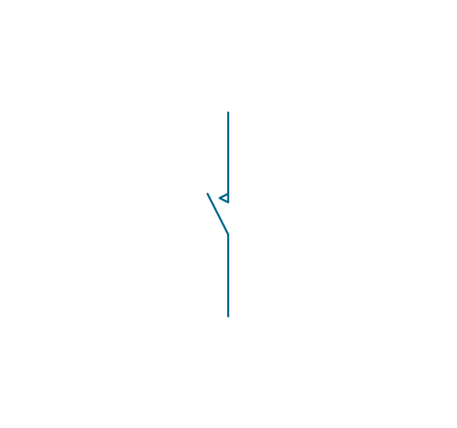
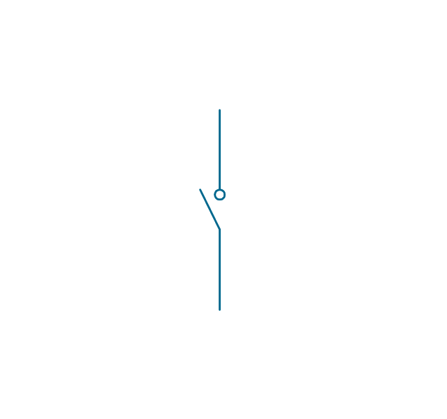
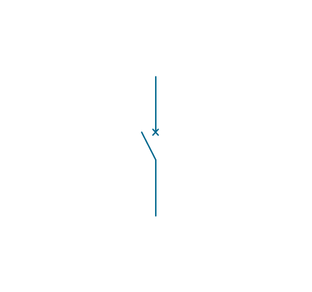
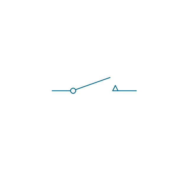
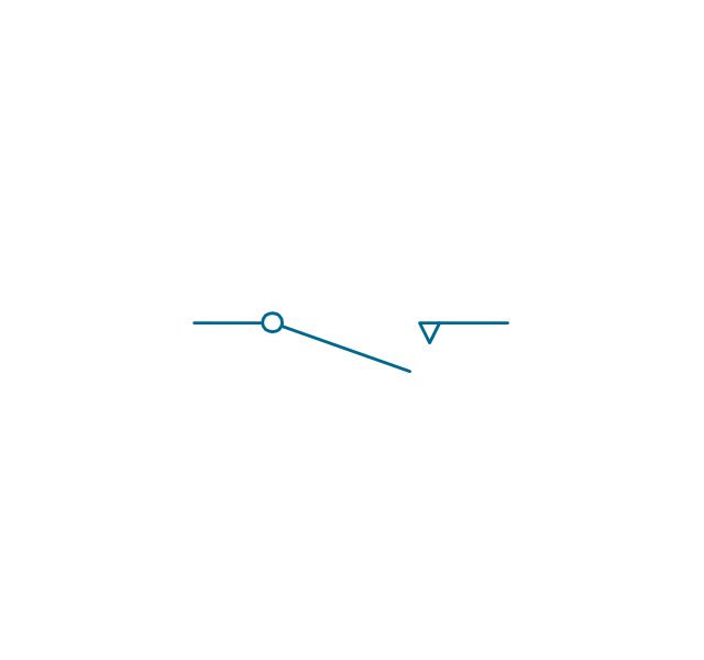
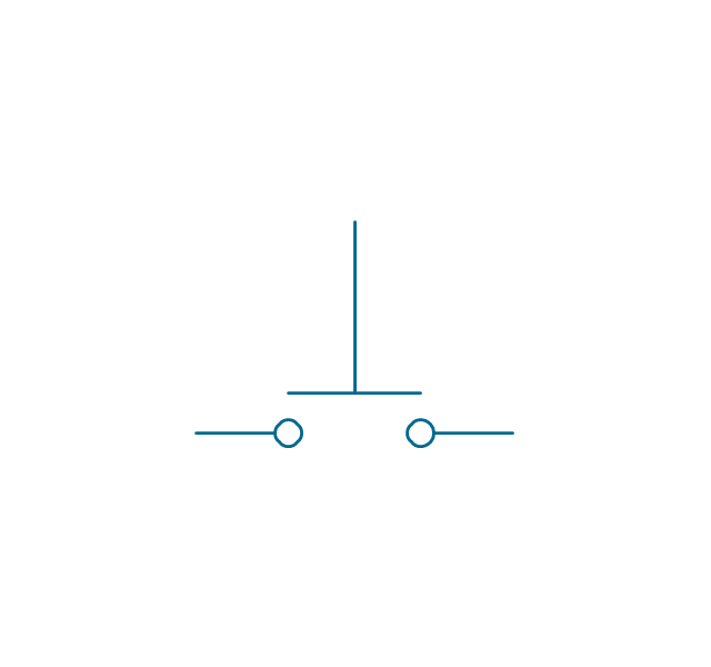
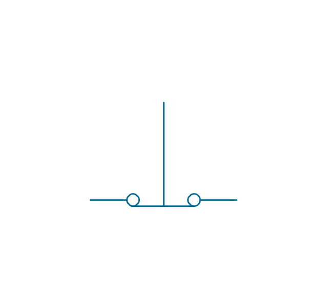
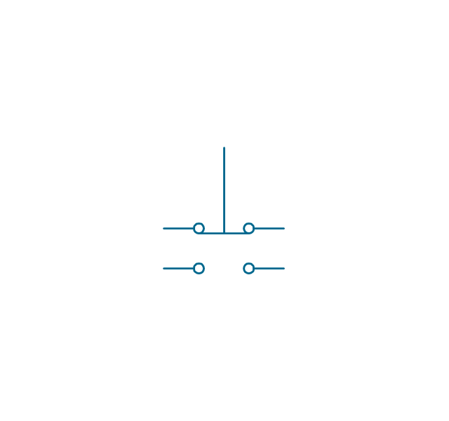
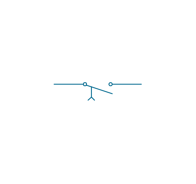
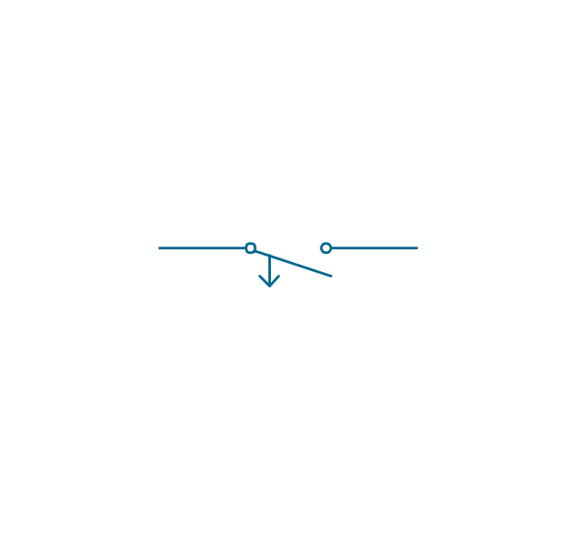
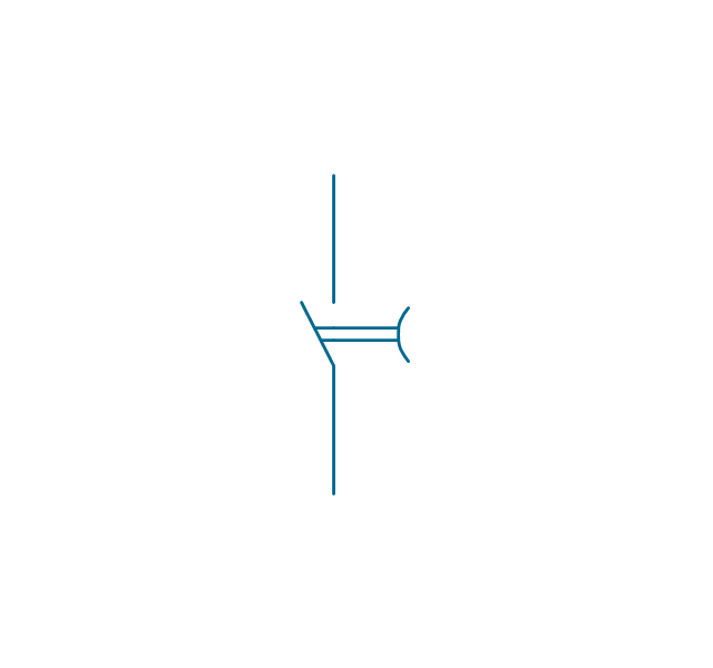
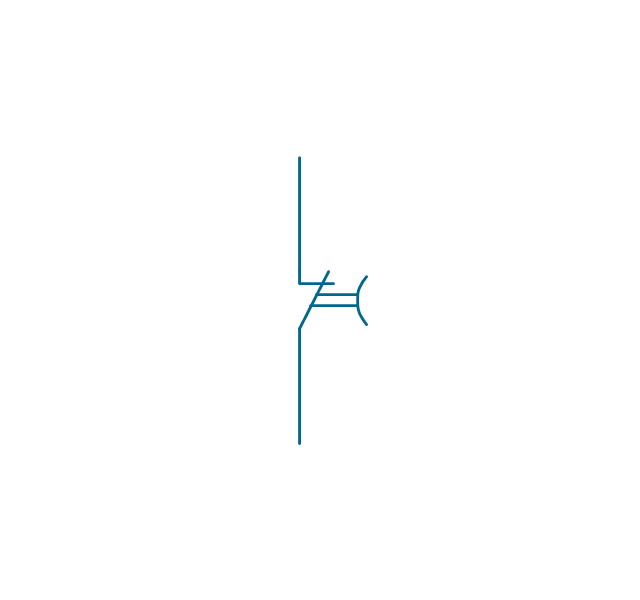
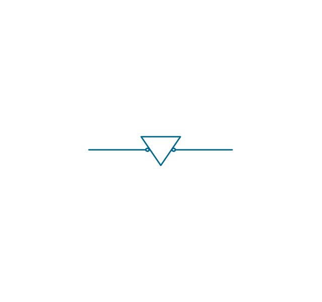
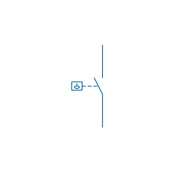
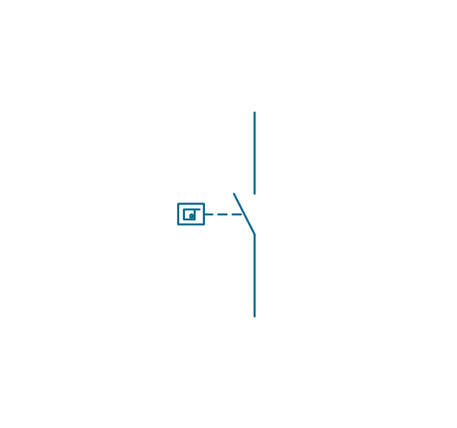
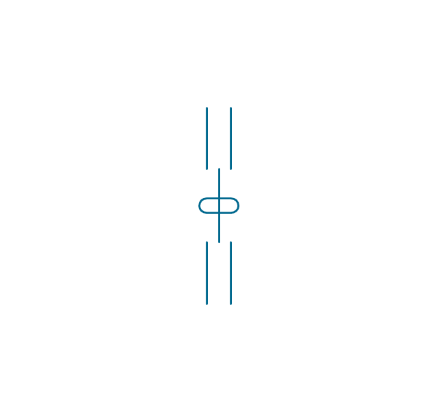
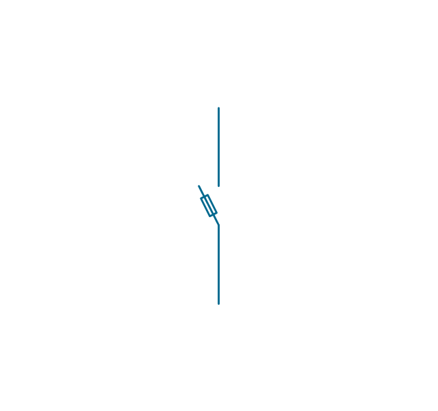
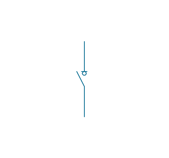
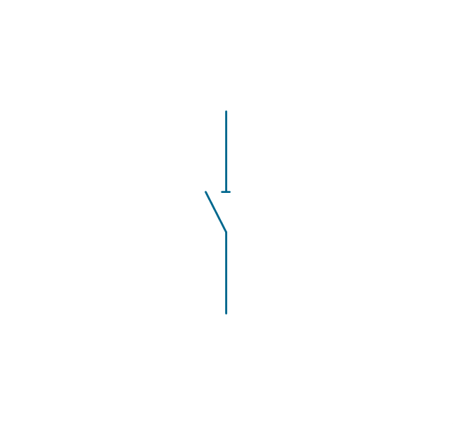
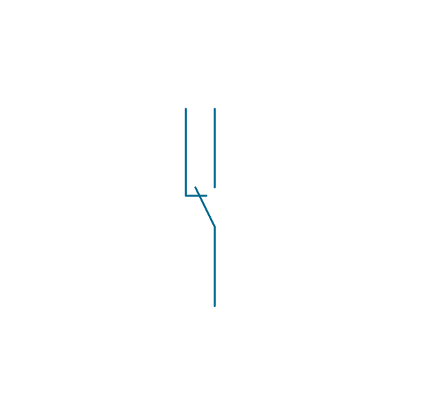
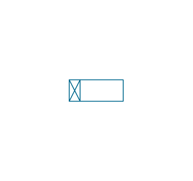
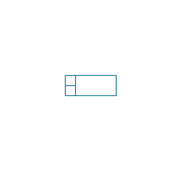
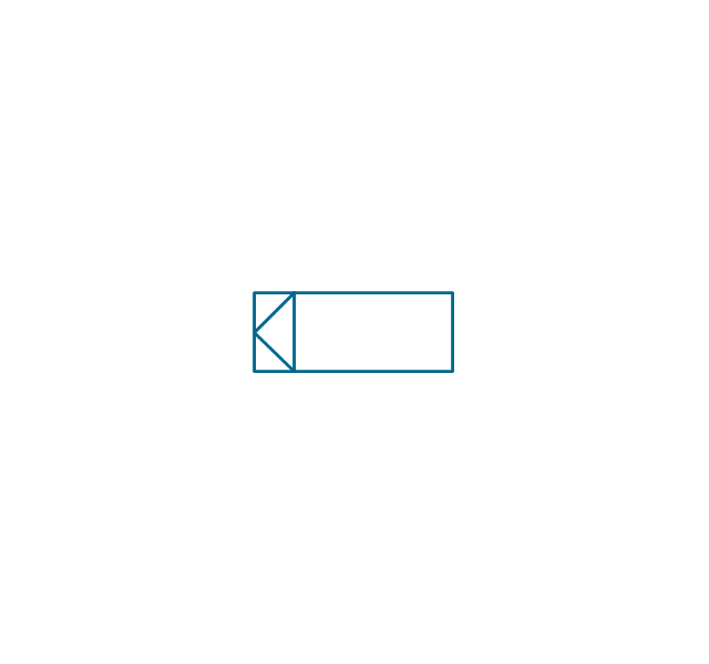
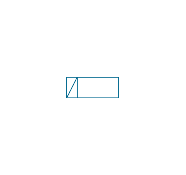
The vector stencils library "Switches" contains 25 symbols of electrical switches.
Use it for drawing electrical design floor and building plans, devices and equipment layouts in the ConceptDraw PRO diagramming and vector drawing software extended with the Electric and Telecom Plans solution from the Building Plans area of ConceptDraw Solution Park.
www.conceptdraw.com/ solution-park/ building-electric-telecom-plans
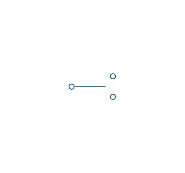
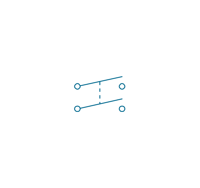
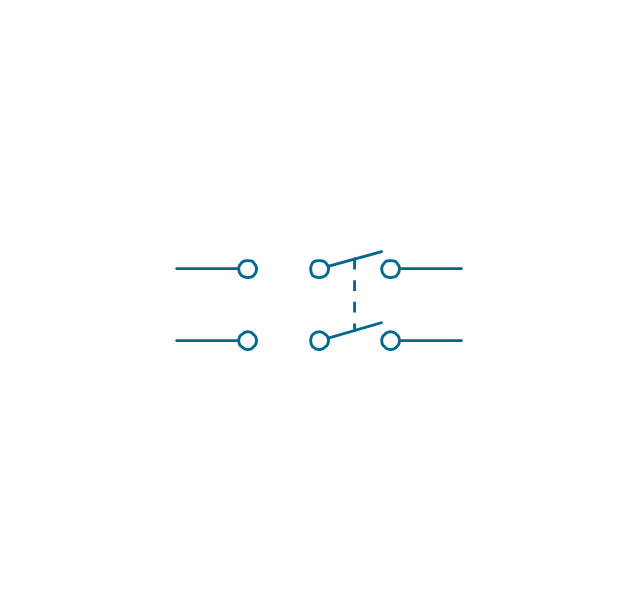
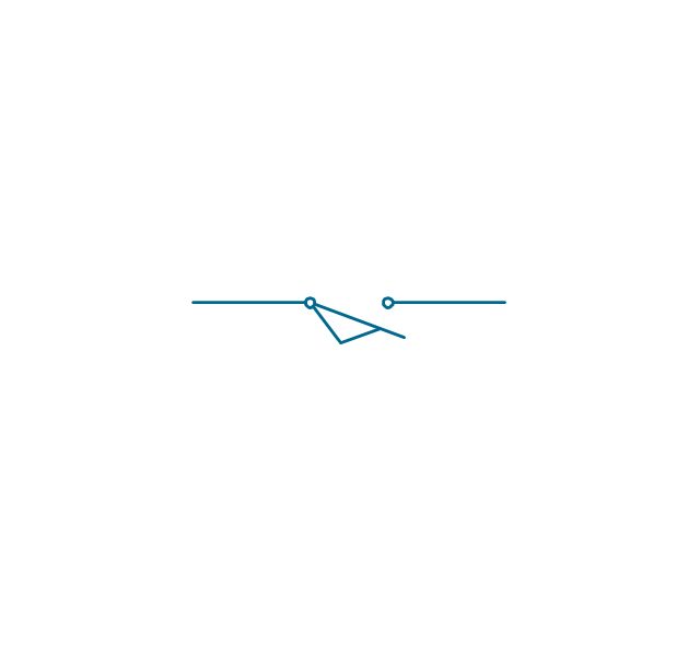
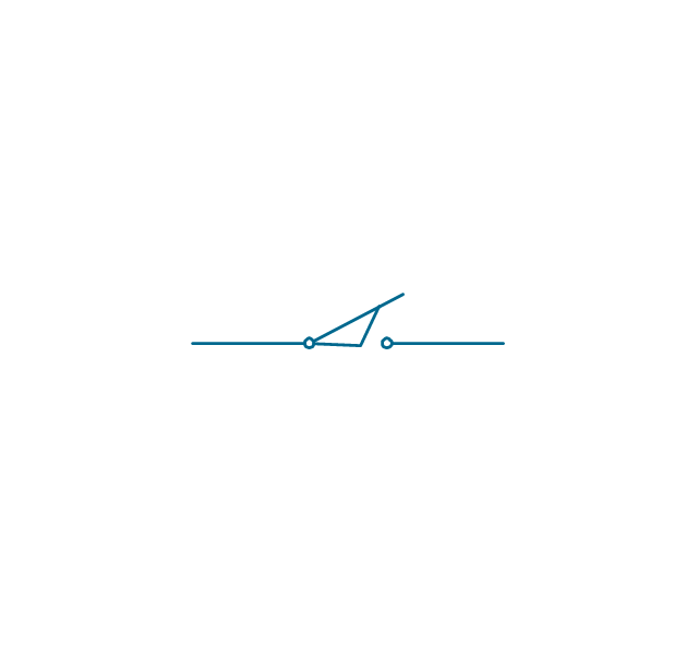
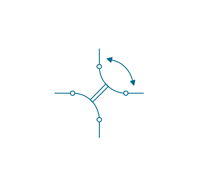
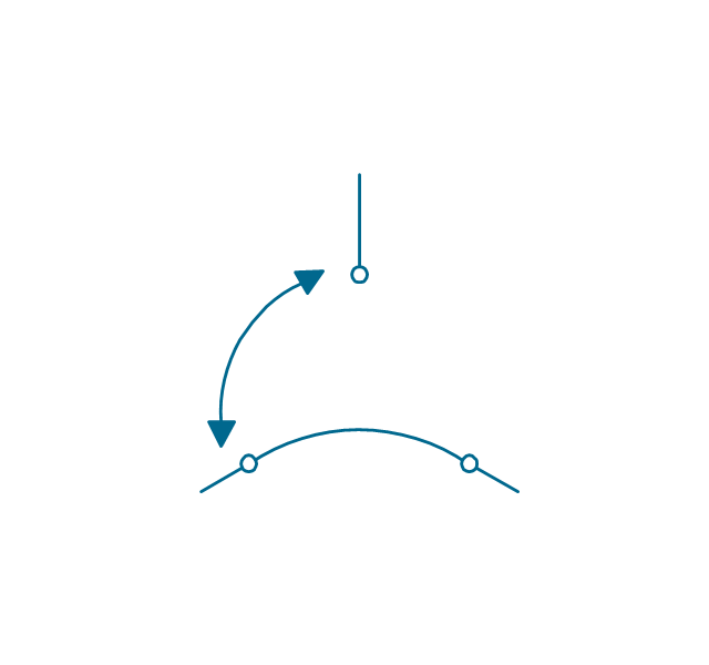
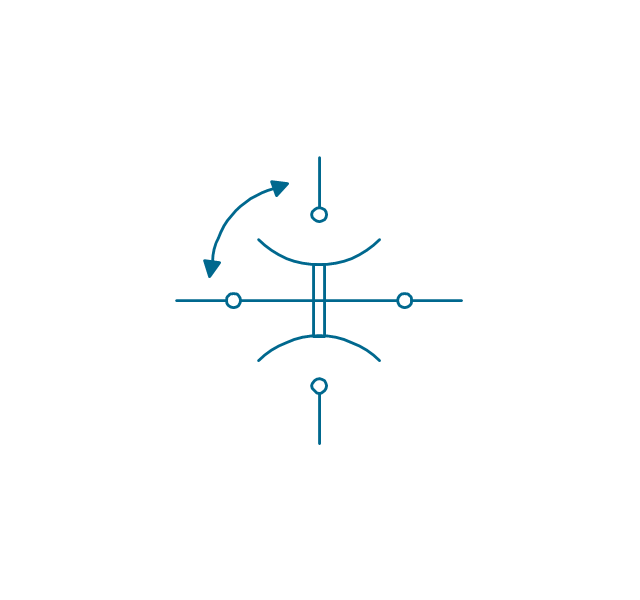
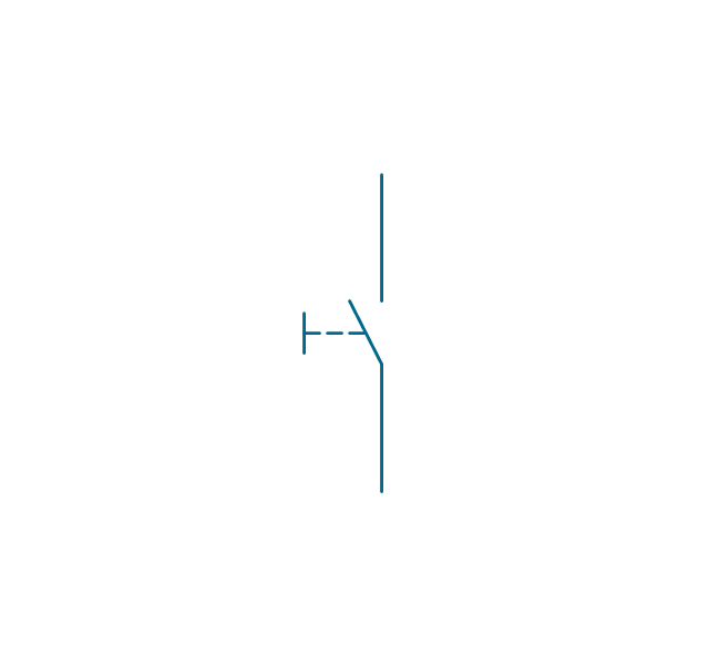
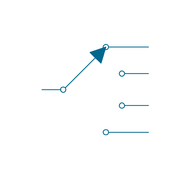
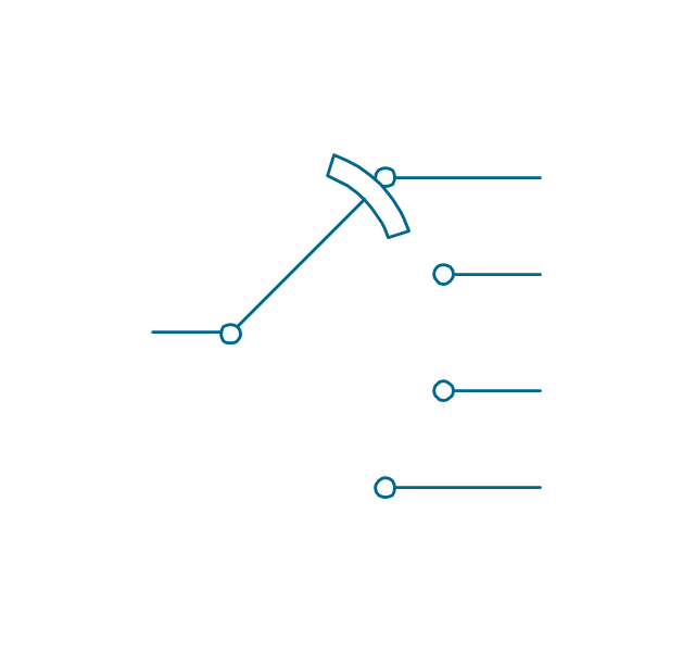
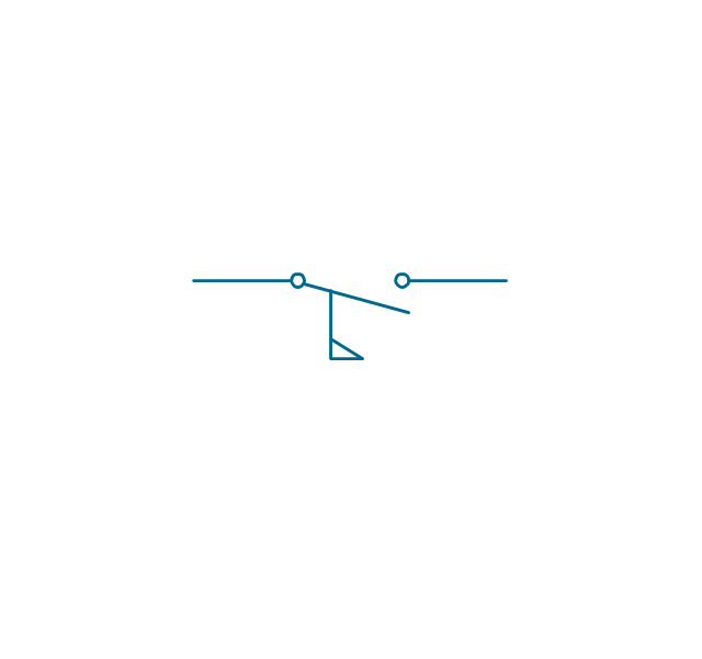
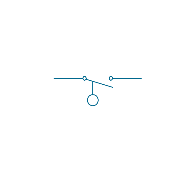
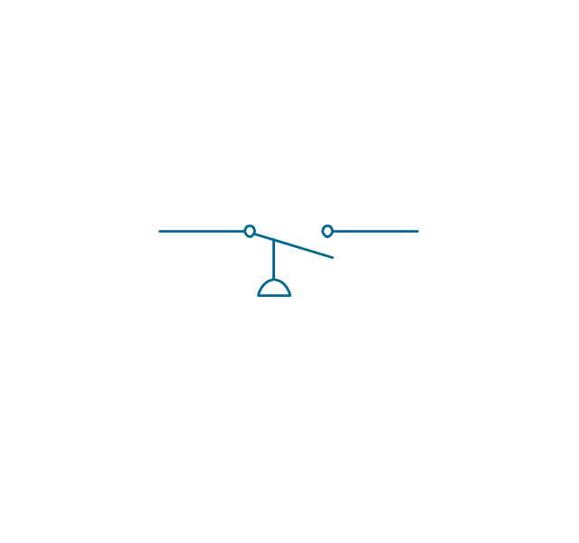
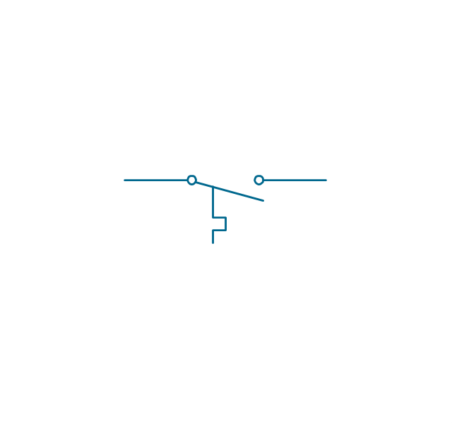
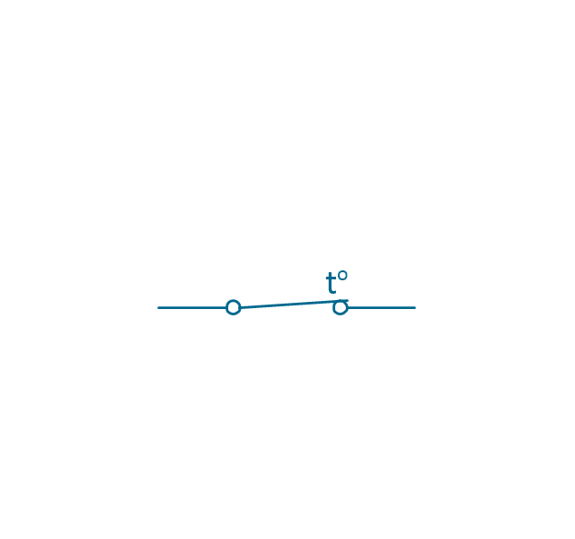
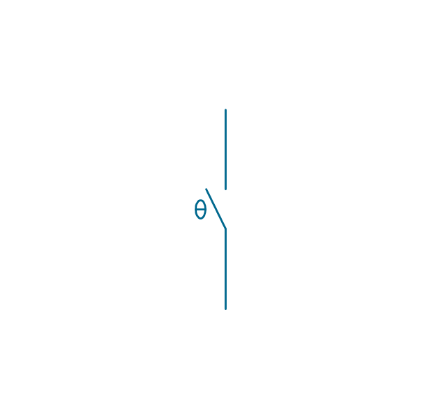
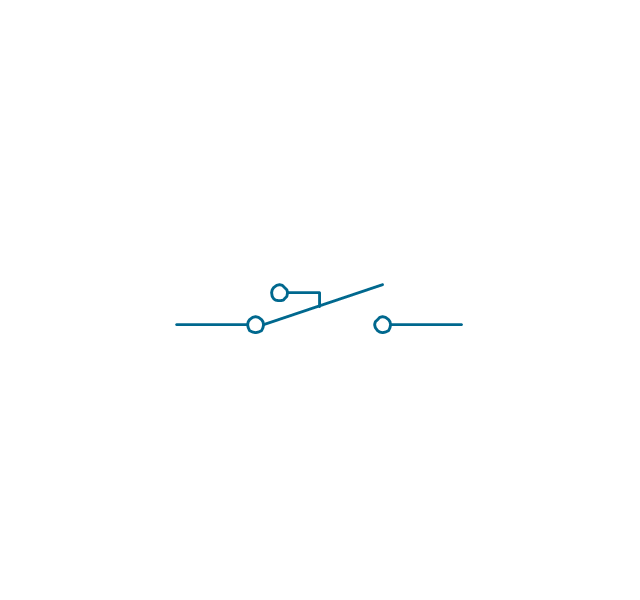
The vector stencils library "Switches and relays" contains 58 symbols of electrical contacts, switches, relays, circuit breakers, selectors, connectors, disconnect devices, switching circuits, current regulators, and thermostats for electrical devices.
Use these shapes for drawing electrical diagrams in the ConceptDraw PRO diagramming and vector drawing software extended with the Electrical Engineering solution from the Engineering area of ConceptDraw Solution Park.
www.conceptdraw.com/ solution-park/ engineering-electrical
Use these shapes for drawing electrical diagrams in the ConceptDraw PRO diagramming and vector drawing software extended with the Electrical Engineering solution from the Engineering area of ConceptDraw Solution Park.
www.conceptdraw.com/ solution-park/ engineering-electrical
The vector stencils library "Switches" contains 25 symbols of electrical switches.
Use it for drawing electrical design floor and building plans, devices and equipment layouts in the ConceptDraw PRO diagramming and vector drawing software extended with the Electric and Telecom Plans solution from the Building Plans area of ConceptDraw Solution Park.
www.conceptdraw.com/ solution-park/ building-electric-telecom-plans
Use it for drawing electrical design floor and building plans, devices and equipment layouts in the ConceptDraw PRO diagramming and vector drawing software extended with the Electric and Telecom Plans solution from the Building Plans area of ConceptDraw Solution Park.
www.conceptdraw.com/ solution-park/ building-electric-telecom-plans
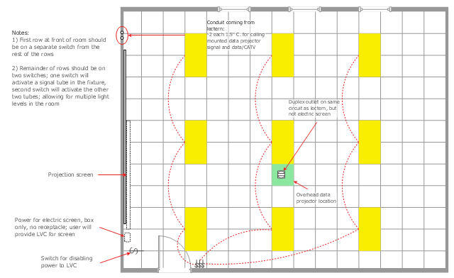
This example was drawn on the base of the reflected ceiling plan from website of Elon University, Elon, NC.
[elon.edu/ docs/ e-web/ bft/ cmdept/ Reflected%20 Ceiling.JPG]
"An overhead projector is a variant of slide projector that is used to display images to an audience. ...
Use in education.
The overhead projector facilitates an easy low-cost interactive environment for educators. Teaching materials can be pre-printed on plastic sheets, upon which the educator can directly write using a non-permanent, washable color marking pen. This saves time, since the transparency can be pre-printed and used repetitively, rather than having materials written manually before each class.
The overhead is typically placed at a comfortable writing height for the educator and allows the educator to face the class, facilitating better communication between the students and teacher. The enlarging features of the projector allow the educator to write in a comfortable small script in a natural writing position rather than writing in an overly large script on a blackboard and having to constantly hold his arm out in midair to write on the blackboard.
When the transparency sheet is full of written or drawn material, it can simply be replaced with a new, fresh sheet with more pre-printed material, again saving class time vs a blackboard that would need to be erased and teaching materials rewritten by the educator. Following the class period, the transparencies are easily restored to their original unused state by washing off with soap and water." [Overhead projector. Wikipedia]
The reflected ceiling plan example "Classroom and computer lab with overhead projector" was created using the ConceptDraw PRO diagramming and vector drawing software extended with the Reflected Ceiling Plans solution from the Building Plans area of ConceptDraw Solution Park.
The vector stencils library "Lighting" contains 55 symbols of lighting devices and equipment.
Use these shapes for drawing lighting design floor plans, circuit schematic and wiring diagrams, cabling layouts, and reflected ceiling plans in the ConceptDraw PRO diagramming and vector drawing software extended with the Electric and Telecom Plans solution from the Building Plans area of ConceptDraw Solution Park.
www.conceptdraw.com/ solution-park/ building-electric-telecom-plans
The vector stencils library "Electrical and telecom" contains 83 symbols of electrical and telecommunication equipment.
Use these shapes for drawing electrical and telecom system design floor plans, cabling layout schemes, and wiring diagrams in the ConceptDraw PRO diagramming and vector drawing software extended with the Electric and Telecom Plans solution from the Building Plans area of ConceptDraw Solution Park.
www.conceptdraw.com/ solution-park/ building-electric-telecom-plans
The vector stencils library "Lighting" contains 55 symbols of lighting devices and equipment.
Use these shapes for drawing lighting design floor plans, circuit schematic and wiring diagrams, cabling layouts, and reflected ceiling plans in the ConceptDraw PRO diagramming and vector drawing software extended with the Electric and Telecom Plans solution from the Building Plans area of ConceptDraw Solution Park.
www.conceptdraw.com/ solution-park/ building-electric-telecom-plans
Use these shapes for drawing lighting design floor plans, circuit schematic and wiring diagrams, cabling layouts, and reflected ceiling plans in the ConceptDraw PRO diagramming and vector drawing software extended with the Electric and Telecom Plans solution from the Building Plans area of ConceptDraw Solution Park.
www.conceptdraw.com/ solution-park/ building-electric-telecom-plans
The vector stencils library "Terminals and connectors" contains 43 element symbols of terminals, connectors, plugs, polarized connectors, jacks, coaxial cables, and conductors.
Use it for drawing the wiring diagrams, electrical layouts, electronic schematics, and circuit diagrams.
"An electrical connector is an electro-mechanical device for joining electrical circuits as an interface using a mechanical assembly. Connectors consist of plugs (male-ended) and jacks (female-ended). The connection may be temporary, as for portable equipment, require a tool for assembly and removal, or serve as a permanent electrical joint between two wires or devices. An adapter can be used to effectively bring together dissimilar connectors.
There are hundreds of types of electrical connectors. Connectors may join two lengths of flexible copper wire or cable, or connect a wire or cable or optical interface to an electrical terminal.
In computing, an electrical connector can also be known as a physical interface... Cable glands, known as cable connectors in the US, connect wires to devices mechanically rather than electrically and are distinct from quick-disconnects performing the latter." [Electrical connector. Wikipedia]
"A terminal is the point at which a conductor from an electrical component, device or network comes to an end and provides a point of connection to external circuits. A terminal may simply be the end of a wire or it may be fitted with a connector or fastener. In network analysis, terminal means a point at which connections can be made to a network in theory and does not necessarily refer to any real physical object. In this context, especially in older documents, it is sometimes called a "pole".
The connection may be temporary, as seen in portable equipment, may require a tool for assembly and removal, or may be a permanent electrical joint between two wires or devices.
All electric cell have two terminals. The first is the positive terminal and the second is the negative terminal. The positive terminal looks like a metal cap and the negative terminal looks like a metal disc. The current flows from the positive terminal, and out through the negative terminal, replicative of current flow (positive (+) to negative (-) flow)." [Terminal (electronics). Wikipedia]
The shapes example "Design elements - Terminals and connectors" was drawn using the ConceptDraw PRO diagramming and vector drawing software extended with the Electrical Engineering solution from the Engineering area of ConceptDraw Solution Park.
- Master Single Pole Switch
- Low Voltage Pole Electrical Symbols
- Switches - Vector stencils library | Outlets - Vector stenvils library ...
- Switches - Vector stencils library | Electrical and telecom - Vector ...
- Design elements - Lighting | Design elements - Switches | Design ...
- Design elements - Switches | Cisco Switches and Hubs. Cisco icons ...
- Switches - Vector stencils library
- Design elements - Switches | Switches - Vector stencils library ...
- Design elements - Switches | Switches - Vector stencils library ...
- Switches and relays - Vector stencils library | Electrical and telecom ...
- Switches and relays - Vector stencils library | Design elements ...
- Single Lamp Symbol
- Switches and relays - Vector stencils library | Switches - Vector ...
- Classroom and computer lab with overhead projector - Reflected ...
- Electrical Drawing Software | Lighting and switch layout | Outlets ...
- Design elements - Lighting | Design elements - Transmission paths ...
- Lighting - Vector stencils library | Design elements - Lighting ...
- Cisco Switches and Hubs. Cisco icons, shapes, stencils and ...
- Electrical Diagram Symbols | How To use House Electrical Plan ...
- How To use House Electrical Plan Software | How To use Electrical ...
