The vector stenvils library "Outlets" contains 57 symbols of electrical outlets.
Use these shapes for drawing building interior design, electrical floor plans and layouts of AC power plugs and sockets in the ConceptDraw PRO diagramming and vector drawing software.
The vector stencils library "Outlets" is included in the Electric and Telecom Plans solution from the Building Plans area of ConceptDraw Solution Park.
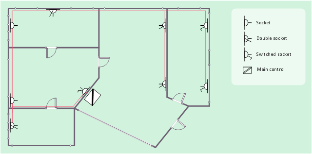
This electrical floot plan sample shows the Power socket outlet layout.
"The term plug is in general and technical use in all forms of English, common alternatives being power plug, electric plug, and (in the UK) plug top. The normal technical term (in both British and International English) for an AC power socket is socket-outlet, but in non-technical common use a number of other terms are used. In British English the general term is socket, but there are numerous common alternatives, including power point, plug socket, wall socket, and wall plug. In American English receptacle and outlet are common, sometimes with qualifiers such as wall outlet, electrical outlet and electrical receptacle, all of these sometimes to be found in the same document. A socket may be surrounded by a decorative and/ or protective cover called a wall plate, face plate, outlet cover, socket cover, or wall cover. In some designs this is an integral piece with the socket itself, bought and installed as a single unit." [AC power plugs and sockets. Wikipedia]
The electrical floot plan example "Power socket outlet layout" was created using the ConceptDraw PRO diagramming and vector drawing software extended with the Electric and Telecom Plans solution from the Building plans area of ConceptDraw Solution Park.
Electrical Symbols, Electrical Diagram Symbols
When drawing Electrical Schematics, Electrical Circuit Diagrams, Power Systems Diagrams, Circuit and Wiring Diagrams, Digital and Analog Logic Schemes, you will obligatory need the electrical symbols and pictograms to represent various electrical and electronic devices, such as resistors, wires, transistors, inductors, batteries, switches, lamps, readouts, amplifiers, repeaters, relays, transmission paths, semiconductors, generators, and many more. Today these symbols are internationally standardized, so the diagrams designed using them are recognizable and comprehensible by specialists from different countries. Electrical Engineering Solution included to ConceptDraw Solution Park provides 26 libraries with 926 commonly used electrical schematic and electrical engineering symbols making the reality the easy drawing of Electrical diagrams, schematics and blueprints. Now you need only a few minutes to create great-looking Electrical diagram, simply choose required electrical design elements from the libraries, drag them on the needed places at the document and connect in a suitable way.How To use House Electrical Plan Software
How we can conduct the electricity at house correctly without a plan? It is impossible. The House electrical diagram depicts locations of switches, outlets, dimmers and lights, and lets understand how you will connect them. But design of House Electrical Plan looks a complex task at a glance, which requires a lot of tools and special experience. But now all is simple with all-inclusive floor plan software - ConceptDraw PRO. As a house electrical plan software, the ConceptDraw PRO contains libraries with a large range of professional lighting and electrical symbols, ready-to-use electrical plans samples and examples, and built-in templates for creating great-looking Home floor electrical plans. It is a fastest way to draw Electrical circuit diagrams, Electrical wiring and Circuit schematics, Digital circuits, Electrical equipment, House electrical plans, Satellite television, Cable television, Home cinema, Closed-circuit television when are used the tools of Electric and Telecom Plans Solution from ConceptDraw Solution Park. Files created in Visio for Mac app can be easily imported to ConceptDraw PRO. Also you may import stencils and even libraries. Try for free an alternative to Visio that Apple users recommend.
Electrical Symbols — Terminals and Connectors
An electrical connector, is an electro-mechanical device used to join electrical terminations and create an electrical circuit. Electrical connectors consist of plugs (male-ended) and jacks (female-ended). The connection may be temporary, as for portable equipment, require a tool for assembly and removal, or serve as a permanent electrical joint between two wires or devices. 26 libraries of the Electrical Engineering Solution of ConceptDraw PRO make your electrical diagramming simple, efficient, and effective. You can simply and quickly drop the ready-to-use objects from libraries into your document to create the electrical diagram."The Ethernet physical layer is the physical layer component of the Ethernet family of computer network standards.
The Ethernet physical layer evolved over a considerable time span and encompasses quite a few physical media interfaces and several magnitudes of speed. The speed ranges from 1 Mbit/ s to 100 Gbit/ s, while the physical medium can range from bulky coaxial cable to twisted pair and optical fiber. In general, network protocol stack software will work similarly on all physical layers.
10-gigabit Ethernet was already used in both enterprise and carrier networks by 2007, with 40 Gbit/ s and 100 Gbit/ s Ethernet ratified. ...
Many Ethernet adapters and switch ports support multiple speeds, using autonegotiation to set the speed and duplex for the best values supported by both connected devices. If auto-negotiation fails, a multiple-speed device will sense the speed used by its partner, but will assume half-duplex. A 10/ 100 Ethernet port supports 10BASE-T and 100BASE-TX. A 10/ 100/ 1000 Ethernet port supports 10BASE-T, 100BASE-TX, and 1000BASE-T." [Ethernet physical layer. Wikipedia]
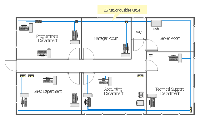
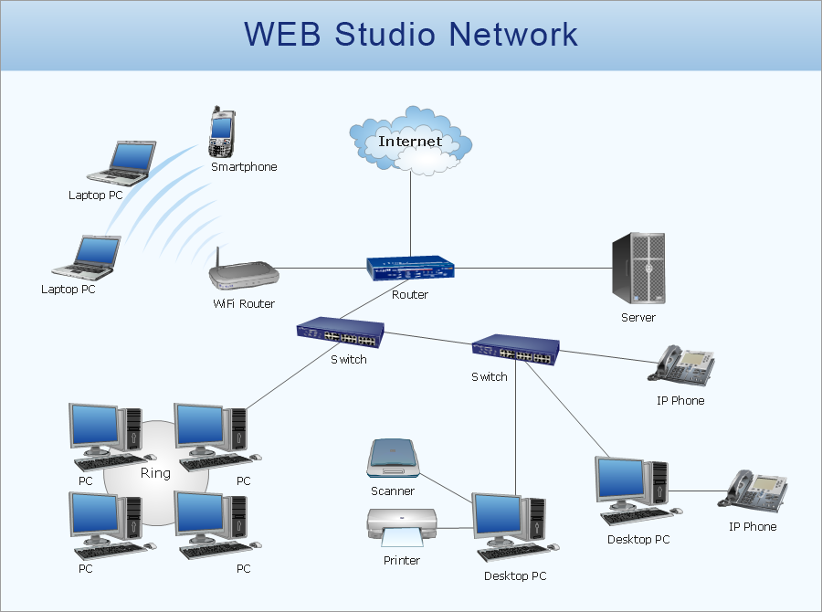
The LAN equipment and cabling layout floorplan example "Ethernet local area network layout floor plan" was created using the ConceptDraw PRO diagramming and vector drawing software extended with the Network Layout Floor Plans solution from the Computer and Networks area of ConceptDraw Solution Park.
Network Printer
Special libraries of highly detailed, accurate shapes and computer graphics, servers, hubs, switches, printers, mainframes, face plates, routers etc.
The vector stencils library "Electrical and telecom" contains 83 symbols of electrical and telecommunication equipment.
Use these shapes for drawing electrical and telecom system design floor plans, cabling layout schemes, and wiring diagrams in the ConceptDraw PRO diagramming and vector drawing software.
The vector stencils library "Electrical and telecom" is included in the Electric and Telecom Plans solution from the Building Plans area of ConceptDraw Solution Park.
This reflected ceiling plan example shows the lighting scheme of computer lab with overhead projector. It was drawn on the base of the RCP from website of Elon University, Elon, NC.
[elon.edu/ docs/ e-web/ bft/ cmdept/ Reflected%20 Ceiling.JPG]
"An overhead projector is a variant of slide projector that is used to display images to an audience. ...
Use in education.
The overhead projector facilitates an easy low-cost interactive environment for educators. Teaching materials can be pre-printed on plastic sheets, upon which the educator can directly write using a non-permanent, washable color marking pen. This saves time, since the transparency can be pre-printed and used repetitively, rather than having materials written manually before each class.
The overhead is typically placed at a comfortable writing height for the educator and allows the educator to face the class, facilitating better communication between the students and teacher. The enlarging features of the projector allow the educator to write in a comfortable small script in a natural writing position rather than writing in an overly large script on a blackboard and having to constantly hold his arm out in midair to write on the blackboard.
When the transparency sheet is full of written or drawn material, it can simply be replaced with a new, fresh sheet with more pre-printed material, again saving class time vs a blackboard that would need to be erased and teaching materials rewritten by the educator. Following the class period, the transparencies are easily restored to their original unused state by washing off with soap and water." [Overhead projector. Wikipedia]
The classroom reflected ceiling plan example "Computer lab RCP" was created using the ConceptDraw PRO diagramming and vector drawing software extended with the Reflected Ceiling Plans solution from the Building Plans area of ConceptDraw Solution Park.
- Duplex Triplex Single Convenience Outlet
- Floor Special-purpose Outlet
- Special Purpose Outlet Symbol
- Single Rectaple Outlet Symbol
- Receptacle And Plug Symbol
- Outlets - Vector stenvils library | Split Receptacle Symbol
- Special Purpose Outlet Symbols
- Outlets - Vector stenvils library | Design elements - Outlets | Outlets ...
- Drop Outlet
- Radio Outlet


