HelpDesk
How to Set Line Jumps for Smart Connectors in ConceptDraw PRO

Ice Hockey Rink Dimensions

ConceptDraw Arrows10 Technology

Basic Flowchart Symbols and Meaning


The vector stencils library "Logical symbols" contains 49 logical symbols for drawing logical network topology diagrams.
"Logical topology, or signal topology, is the arrangement of devices on a computer network and how they communicate with one another. How devices are connected to the network through the actual cables that transmit data, or the physical structure of the network, is called the physical topology. Physical topology defines how the systems are physically connected. It represents the physical layout of the devices on the network. The logical topology defines how the systems communicate across the physical topologies.
Logical topologies are bound to network protocols and describe how data is moved across the network. ... EXAMPLE : twisted pair Ethernet is a logical bus topology in a physical star topology layout. While IBM's token ring is a logical ring topology, it is physically set up in star topology." [Logical topology. Wikipedia]
The icons example "Logical symbols - Vector stencils library" was created using the ConceptDraw PRO diagramming and vector drawing software extended with the Computer and Networks solution from the Computer and Networks area of ConceptDraw Solution Park.
www.conceptdraw.com/ solution-park/ computer-and-networks
Coaxial Line Tag

Fiber Optic Line Tag

Twisted Pair Line Tag

SC2200 Signaling Controller

Bridge

Network Management Appliance

Access Server (Communications Server)
-logical-symbols---vector-stencils-library.png--diagram-flowchart-example.png)
Terminal Server

Web Browser

Security Management, Cisco

Lock and Key

Lock

Key

Relational Database

Host

CSU/DSU

WAN

University

Government building

Home Office

Telecommuter House PC

Medium Building, Regular

Headquarters, Subdued

House, Regular

Small Business

Network Connector

Dynamic Connector

Line Connector

Line-curve Connector

Bus

FDDI Ring

Peer-to-peer

Token-ring

Star

Comm-link

Curved Bus

Ethernet

Cloud

Speaker

Microphone

Router

ATM Router

ISDN Switch

ATM Switch

ATM/FastGB Etherswitch

Workgroup Switch

Small Hub

100BaseT Hub

CDDI-FDDI

ERD Symbols and Meanings


The vector stencils library "Logical symbols" contains 49 logical symbols for drawing logical network topology diagrams.
"Logical topology, or signal topology, is the arrangement of devices on a computer network and how they communicate with one another. How devices are connected to the network through the actual cables that transmit data, or the physical structure of the network, is called the physical topology. Physical topology defines how the systems are physically connected. It represents the physical layout of the devices on the network. The logical topology defines how the systems communicate across the physical topologies.
Logical topologies are bound to network protocols and describe how data is moved across the network. ... EXAMPLE : twisted pair Ethernet is a logical bus topology in a physical star topology layout. While IBM's token ring is a logical ring topology, it is physically set up in star topology." [Logical topology. Wikipedia]
The icons example "Logical symbols - Vector stencils library" was created using the ConceptDraw PRO diagramming and vector drawing software extended with the Computer and Networks solution from the Computer and Networks area of ConceptDraw Solution Park.
www.conceptdraw.com/ solution-park/ computer-and-networks
"Logical topology, or signal topology, is the arrangement of devices on a computer network and how they communicate with one another. How devices are connected to the network through the actual cables that transmit data, or the physical structure of the network, is called the physical topology. Physical topology defines how the systems are physically connected. It represents the physical layout of the devices on the network. The logical topology defines how the systems communicate across the physical topologies.
Logical topologies are bound to network protocols and describe how data is moved across the network. ... EXAMPLE : twisted pair Ethernet is a logical bus topology in a physical star topology layout. While IBM's token ring is a logical ring topology, it is physically set up in star topology." [Logical topology. Wikipedia]
The icons example "Logical symbols - Vector stencils library" was created using the ConceptDraw PRO diagramming and vector drawing software extended with the Computer and Networks solution from the Computer and Networks area of ConceptDraw Solution Park.
www.conceptdraw.com/ solution-park/ computer-and-networks
Coaxial Line Tag
Fiber Optic Line Tag
Twisted Pair Line Tag
SC2200 Signaling Controller
Bridge
Network Management Appliance
Access Server (Communications Server)
Terminal Server
Web Browser
Security Management, Cisco
Lock and Key
Lock
Key
Relational Database
Host
CSU/DSU
WAN
University
Government building
Home Office
Telecommuter House PC
Medium Building, Regular
Headquarters, Subdued
House, Regular
Small Business
Network Connector
Dynamic Connector
Line Connector
Line-curve Connector
Bus
FDDI Ring
Peer-to-peer
Token-ring
Star
Comm-link
Curved Bus
Ethernet
Cloud
Speaker
Microphone
Router
ATM Router
ISDN Switch
ATM Switch
ATM/FastGB Etherswitch
Workgroup Switch
Small Hub
100BaseT Hub
CDDI-FDDI
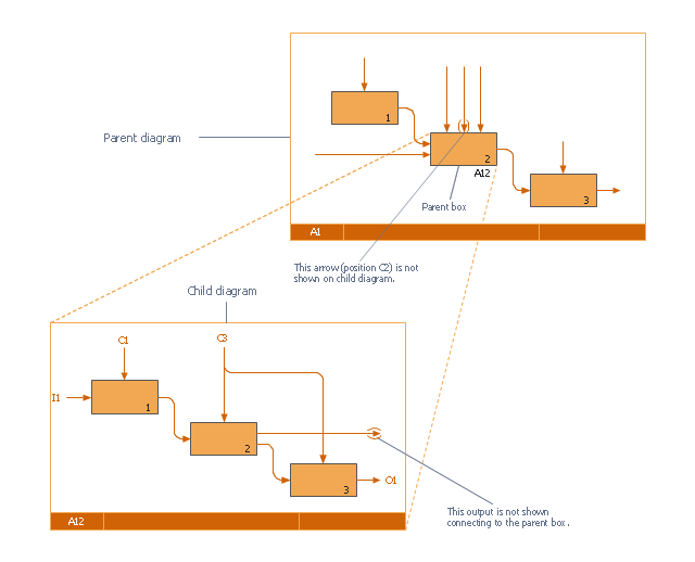
This IDEF0 diagram was redesigned from the Wikimedia Commons file: 18 Example of Tunneled Arrows.svg.
[commons.wikimedia.org/ wiki/ File:18_ Example_ of_ Tunneled_ Arrows.svg]
"Tunneled Arrows.
Arrows that provide information at one level of decomposition but are not needed at another (parent, child) level." [classes.engr.oregonstate.edu/ mime/ fall2013/ ie545-001/ Slides/ class%20 01-3b%20 IDEF0%20 1%20 revised.pdf]
The example "IDEF0 diagram - Tunneled arrows" was created using the ConceptDraw PRO diagramming and vector drawing software extended with the solution "IDEF Business Process Diagrams" from the area "Business Processes" of ConceptDraw Solution Park.
IDEF0 business process diagram
The vector stencils library "Logical symbols" contains 49 logical symbols for drawing logical network topology diagrams.
"Logical topology, or signal topology, is the arrangement of devices on a computer network and how they communicate with one another. How devices are connected to the network through the actual cables that transmit data, or the physical structure of the network, is called the physical topology. Physical topology defines how the systems are physically connected. It represents the physical layout of the devices on the network. The logical topology defines how the systems communicate across the physical topologies.
Logical topologies are bound to network protocols and describe how data is moved across the network. ... EXAMPLE : twisted pair Ethernet is a logical bus topology in a physical star topology layout. While IBM's token ring is a logical ring topology, it is physically set up in star topology." [Logical topology. Wikipedia]
The icons example "Logical symbols - Vector stencils library" was created using the ConceptDraw PRO diagramming and vector drawing software extended with the Computer and Networks solution from the Computer and Networks area of ConceptDraw Solution Park.
www.conceptdraw.com/ solution-park/ computer-and-networks
"Logical topology, or signal topology, is the arrangement of devices on a computer network and how they communicate with one another. How devices are connected to the network through the actual cables that transmit data, or the physical structure of the network, is called the physical topology. Physical topology defines how the systems are physically connected. It represents the physical layout of the devices on the network. The logical topology defines how the systems communicate across the physical topologies.
Logical topologies are bound to network protocols and describe how data is moved across the network. ... EXAMPLE : twisted pair Ethernet is a logical bus topology in a physical star topology layout. While IBM's token ring is a logical ring topology, it is physically set up in star topology." [Logical topology. Wikipedia]
The icons example "Logical symbols - Vector stencils library" was created using the ConceptDraw PRO diagramming and vector drawing software extended with the Computer and Networks solution from the Computer and Networks area of ConceptDraw Solution Park.
www.conceptdraw.com/ solution-park/ computer-and-networks
Coaxial Line Tag
Fiber Optic Line Tag
Twisted Pair Line Tag
SC2200 Signaling Controller
Bridge
Network Management Appliance
Access Server (Communications Server)
Terminal Server
Web Browser
Security Management, Cisco
Lock and Key
Lock
Key
Relational Database
Host
CSU/DSU
WAN
University
Government building
Home Office
Telecommuter House PC
Medium Building, Regular
Headquarters, Subdued
House, Regular
Small Business
Network Connector
Dynamic Connector
Line Connector
Line-curve Connector
Bus
FDDI Ring
Peer-to-peer
Token-ring
Star
Comm-link
Curved Bus
Ethernet
Cloud
Speaker
Microphone
Router
ATM Router
ISDN Switch
ATM Switch
ATM/FastGB Etherswitch
Workgroup Switch
Small Hub
100BaseT Hub
CDDI-FDDI