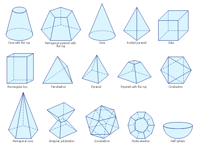
The vector stencils library "Solid geometry" contains 15 shapes of solid geometric figures.
"In mathematics, solid geometry was the traditional name for the geometry of three-dimensional Euclidean space - for practical purposes the kind of space we live in. It was developed following the development of plane geometry. Stereometry deals with the measurements of volumes of various solid figures including cylinder, circular cone, truncated cone, sphere, and prisms.
The Pythagoreans had dealt with the regular solids, but the pyramid, prism, cone and cylinder were not studied until the Platonists. Eudoxus established their measurement, proving the pyramid and cone to have one-third the volume of a prism and cylinder on the same base and of the same height, and was probably the discoverer of a proof that the volume of a sphere is proportional to the cube of its radius." [Solid geometry. Wikipedia]
The shapes example "Design elements - Solid geometry" was created using the ConceptDraw PRO diagramming and vector drawing software extended with the Mathematics solution from the Science and Education area of ConceptDraw Solution Park.
Solid geometrical figures
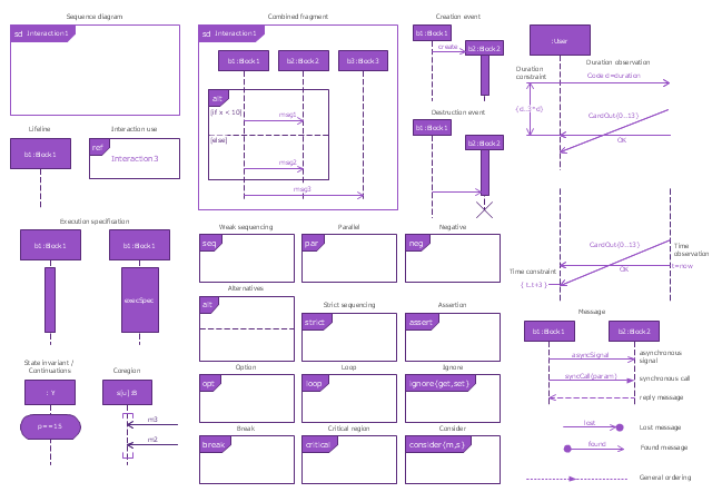
The vector stencils library "Sequence diagram" contains 32 SysML symbols.
Use it to design your sequence diagrams using ConceptDraw PRO diagramming and vector drawing software.
"A sequence diagram shows, as parallel vertical lines (lifelines), different processes or objects that live simultaneously, and, as horizontal arrows, the messages exchanged between them, in the order in which they occur. This allows the specification of simple runtime scenarios in a graphical manner. ...
If the lifeline is that of an object, it demonstrates a role. Leaving the instance name blank can represent anonymous and unnamed instances.
Messages, written with horizontal arrows with the message name written above them, display interaction. Solid arrow heads represent synchronous calls, open arrow heads represent asynchronous messages, and dashed lines represent reply messages. If a caller sends a synchronous message, it must wait until the message is done, such as invoking a subroutine. If a caller sends an asynchronous message, it can continue processing and doesn’t have to wait for a response. Asynchronous calls are present in multithreaded applications and in message-oriented middleware. Activation boxes, or method-call boxes, are opaque rectangles drawn on top of lifelines to represent that processes are being performed in response to the message (ExecutionSpecifications in UML).
Objects calling methods on themselves use messages and add new activation boxes on top of any others to indicate a further level of processing.
When an object is destroyed (removed from memory), an X is drawn on top of the lifeline, and the dashed line ceases to be drawn below it (this is not the case in the first example though). It should be the result of a message, either from the object itself, or another.
A message sent from outside the diagram can be represented by a message originating from a filled-in circle (found message in UML) or from a border of the sequence diagram (gate in UML)." [Sequence diagram. Wikipedia]
The SysML shapes example "Design elements - Sequence diagram" is included in the SysML solution from the Software Development area of ConceptDraw Solution Park.
SysML sequence diagram symbols
The vector stencils library "Bank UML sequence diagram" contains 34 shapes for drawing UML sequence diagrams.
Use it for object-oriented modeling of your bank information system.
"A sequence diagram shows, as parallel vertical lines (lifelines), different processes or objects that live simultaneously, and, as horizontal arrows, the messages exchanged between them, in the order in which they occur. This allows the specification of simple runtime scenarios in a graphical manner.
Diagram building blocks.
If the lifeline is that of an object, it demonstrates a role. Leaving the instance name blank can represent anonymous and unnamed instances.
Messages, written with horizontal arrows with the message name written above them, display interaction. Solid arrow heads represent synchronous calls, open arrow heads represent asynchronous messages, and dashed lines represent reply messages. ...
Activation boxes, or method-call boxes, are opaque rectangles drawn on top of lifelines to represent that processes are being performed in response to the message (ExecutionSpecifications in UML).
Objects calling methods on themselves use messages and add new activation boxes on top of any others to indicate a further level of processing.
When an object is destroyed (removed from memory), an X is drawn on top of the lifeline, and the dashed line ceases to be drawn below it ...
A message sent from outside the diagram can be represented by a message originating from a filled-in circle (found message in UML) or from a border of the sequence diagram (gate in UML)." [Sequence diagram. Wikipedia]
This example of UML sequence diagram symbols for the ConceptDraw PRO diagramming and vector drawing software is included in the ATM UML Diagrams solution from the Software Development area of ConceptDraw Solution Park.
UML sequence diagram symbols

Basic Flowchart Symbols and Meaning


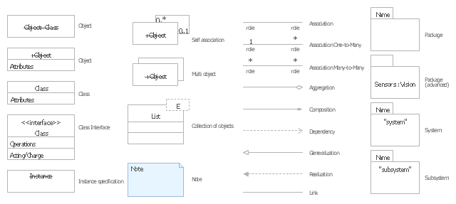
The vector stencils library "UML object diagrams" contains 26 symbols for the ConceptDraw PRO diagramming and vector drawing software.
"Each object and link on an object diagram is represented by an InstanceSpecification. This can show an object's classifier (e.g. an abstract or concrete class) and instance name, as well as attributes and other structural features using slots. Each slot corresponds to a single attribute or feature, and may include a value for that entity.
The name on an instance specification optionally shows an instance name, a ':' separator, and optionally one or more classifier names separated by commas. The contents of slots, if any, are included below the names, in a separate attribute compartment. A link is shown as a solid line, and represents an instance of an association. ...
If you are using a UML modeling tool, you will typically draw object diagrams using some other diagram type, such as on a class diagram. An object instance may be called an instance specification or just an instance. A link between instances is generally referred to as a link. Other UML entities, such as an aggregation or composition symbol (a diamond) may also appear on an object diagram." [Object diagram. Wikipedia]
The example "Design elements - UML object diagrams" is included in the Rapid UML solution from the Software Development area of ConceptDraw Solution Park.
UML object diagram symbols
IDEF3 Standard

IDEF1X Standard

Bubble diagrams with ConceptDraw PRO

Process Flowchart


Bubble diagrams in Landscape Design with ConceptDraw PRO

Scrum process work items and workflow

Network Glossary Definition


- Solid Figure And Its Name
- Design elements - Solid geometry | Pentagonal Cylinder Name
- Design elements - Solid geometry | Names Of Solid Figures Geometry
- Design elements - Solid geometry | Basic Flowchart Symbols and ...
- Mathematics Symbols | Solid geometry - Vector stencils library ...
- Design elements - Solid geometry | Bubble diagrams in Landscape ...
- Design elements - Solid geometry
- Pyramid Diagram | Design elements - Solid geometry | Design ...
- Basic Flowchart Symbols and Meaning | Gometry Diagrams With ...
- Solid Figure Of Geometry
- Scientific Symbols Chart | Design elements - Solid geometry ...
- Design elements - Solid geometry | Scientific Symbols Chart ...
- Solid Diagram Symbols
- Geometric Diagrams With Name
- Mathematics | Design elements - Solid geometry | Mathematics ...
- Solid geometry - Vector stencils library | Platonic solids | Design ...
- Design elements - Solid geometry | Design elements - Optics | Solid ...
- Design elements - Solid geometry | Mathematics | Solid geometry ...
- Design elements - Solid geometry | Mathematics Symbols | Scientific ...
- Mathematics Symbols | Mathematics | Solid geometry - Vector ...