"Data flow diagrams are one of the three essential perspectives of the structured-systems analysis and design method SSADM. The sponsor of a project and the end users will need to be briefed and consulted throughout all stages of a system's evolution. With a data flow diagram, users are able to visualize how the system will operate, what the system will accomplish, and how the system will be implemented. The old system's dataflow diagrams can be drawn up and compared with the new system's data flow diagrams to draw comparisons to implement a more efficient system. Data flow diagrams can be used to provide the end user with a physical idea of where the data they input ultimately has an effect upon the structure of the whole system from order to dispatch to report. How any system is developed can be determined through a data flow diagram model.
In the course of developing a set of levelled data flow diagrams the analyst/ designers is forced to address how the system may be decomposed into component sub-systems, and to identify the transaction data in the data model.
Data flow diagrams can be used in both Analysis and Design phase of the SDLC.
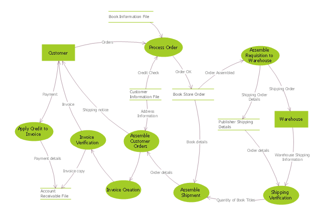
There are different notations to draw data flow diagrams (Yourdon & Coad and Gane & Sarson), defining different visual representations for processes, data stores, data flow, and external entities." [Data flow diagram. Wikipedia]
The DFD (Yourdon and Coad notation) example "Process of account receivable" was created using the ConceptDraw PRO diagramming and vector drawing software extended with the Data Flow Diagrams solution from the Software Development area of ConceptDraw Solution Park.
Applications
ConceptDraw DIAGRAM is a multipurpose software from ConceptDraw suite intended for diagramming, business and technical drawing, and visual documenting. You can reach a lot of practical benefits from the use of ConceptDraw DIAGRAM. The list of ConceptDraw DIAGRAM applications and versatile possibilities is extremely great. Among them network and system diagramming, business diagramming, Cisco network design, network visualization, software and database design, software development, business flowcharting, data flow design, databases modeling and visualization, business processes modeling, business drawing, technical drawing, GUI prototyping, Organizational charts construction, business processes fixing, web site planning and design, Internet solutions design, information architecture design, UML modeling, ER diagrams design, home and landscape design, and a lot of other applications. ConceptDraw DIAGRAM offers the users a beneficial collaboration, compatibility with MS Visio and many other popular programs, including other products from ConceptDraw suite.
 Interactive Voice Response Diagrams
Interactive Voice Response Diagrams solution extends ConceptDraw DIAGRAM software with samples, templates and libraries of ready-to-use vector stencils that help create Interactive Voice Response (IVR) diagrams illustrating in details a work of interactive voice response system, the IVR system’s logical and physical structure, Voice-over-Internet Protocol (VoIP) diagrams, and Action VoIP diagrams with representing voice actions on them, to visualize how the computers interact with callers through voice recognition and dual-tone multi-frequency signaling (DTMF) keypad inputs.
 SYSML
SYSML
The SysML solution helps to present diagrams using Systems Modeling Language; a perfect tool for system engineering.
 Computer and Networks Area
The solutions from Computer and Networks Area of ConceptDraw Solution Park collect samples, templates and vector stencils libraries for drawing computer and network diagrams, schemes and technical drawings.
- Structured Systems Analysis and Design Method (SSADM) with ...
- Process Flowchart | Structured Systems Analysis and Design ...
- Data Flow Diagram Model
- Data structure diagram with ConceptDraw PRO | Structured Systems ...
- LLNL Flow Charts | Structured Systems Analysis and Design Method ...
- Data structure diagram with ConceptDraw PRO | Program Structure ...
- Data structure diagram with ConceptDraw PRO | Structured Systems ...
- Data Flow Diagrams | Structured Systems Analysis and Design ...
- Data Flow Diagrams | Value Stream Mapping | Structured Systems ...
- Total Quality Management with ConceptDraw | Structured Systems ...
- Design elements - Data Flow Diagram (DFD) | How to Create ...
- Organizational Structure | Process Flowchart | Applications | System ...
- Data Flow Diagrams
- UML Diagrams with ConceptDraw PRO | How to Draw a Computer ...
- Fault tree analysis diagram template | Business Productivity ...
- Fishbone Diagram | Data Flow Diagrams | Applications | Library ...
- Data Flow Diagram Process | DFD - Process of account receivable ...
- Data Flow Diagrams with ConceptDraw PRO | Design Data Flow ...
- DFD Library - Design elements | Data Flow Diagrams | Software and ...
- Computer network system design diagram | Diagramming software ...

