FSM — Finite-state Machine

UML State Machine Diagram.Design Elements

Finite State Machine

State Machine Diagram


 Specification and Description Language (SDL)
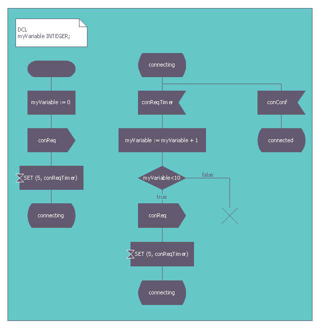
For people in the field of systems engineering or system design, working with specification and description language (sdl) and finite state machines (fsm).
This finite state machine diagram example was redesigned from the Wikimedia Commons file: SdlStateMachine.png. [commons.wikimedia.org/ wiki/ File:SdlStateMachine.png]
This file is licensed under the Creative Commons Attribution-Share Alike 3.0 Unported license. [creativecommons.org/ licenses/ by-sa/ 3.0/ deed.en]
"Behavior.
Each process agent is a state machine that contributes to the action carried out by the system. A message stimulus coming from the environment or from another agent to an agent is called a signal. Signals received by a process agent are first placed in a queue (the input port). When the state machine is waiting in a state, if the first signal in the input port is enabled for that state it starts a transition leading to another state. Transitions can output signals to other agents or to the environment. A process agent is allowed to contain procedure types so that the same actions can be invoked from different places. It is also allowed to call a remote procedure type to invoke a procedure in another agent (or even another system) and wait for a response." [Specification and Description Language. Wikipedia]
The example "SDL diagram - State Machine" was created using the ConceptDraw PRO diagramming and vector drawing software extended with the Specification and Description Language (SDL) solution from the Engineering area of ConceptDraw Solution Park.
Finite state machine
Used Solutions
Diagramming Software for Design UML State Machine Diagrams

"State machine diagram is a behavior diagram which shows discrete behavior of a part of designed system through finite state transitions. State machine diagrams can also be used to express the usage protocol of part of a system. Two kinds of state machines defined in UML 2.4 are:
(1) behavioral state machine, and
(2) protocol state machine.
The following nodes and edges are typically drawn in state machine diagram: behavioral state, behavioral transition, protocol state, protocol transition, different pseudostates. ...
Behavioral state machine is specialization of behavior and is used to specify discrete behavior of a part of designed system through finite state transitions. The state machine formalism used in this case is an object-based variant of Harel statecharts.
Behavior is modeled as a traversal of a graph of state nodes connected with transitions. Transitions are triggered by the dispatching of series of events. During the traversal, the state machine could also execute some activities. ...
Protocol state machine is a specialization of behavioral state machine and is used to express usage protocol or lifecycle of a classifier. It specifies which operations of the classifier can be called in which state and under which condition, thus specifying the allowed call sequences on the classifier’s operations. Protocol state machines express the legal transitions that a classifier can trigger." [uml-diagrams.org/ state-machine-diagrams.html]
The template "UML state machine diagram" for the ConceptDraw PRO diagramming and vector drawing software is included in the Rapid UML solution from the Software Development area of ConceptDraw Solution Park.
www.conceptdraw.com/ solution-park/ software-uml
UML state machine diagram

State Diagram Example — Online Store

Detail Specifications Exchanging Mind Maps with Evernote
UML Diagramming Software

Systems Engineering

UML Notation

UML Diagram for Mac

- State Machine Diagram | Bank UML Diagram | ATM UML Diagrams ...
- Finite State Machine | State Machine Diagram | Systems ...
- Finite State Machine Of Library Management System
- UML state machine diagram - Template | FSM — Finite-state ...
- Finite State Machine Designer Online
- Finite State Machine
- Finite State Machine | UML State Machine Diagram.Design ...
- FSM — Finite - state Machine | UML State Machine Diagram.Design ...
- Finite State Machine Problems And Solutions
- UML State Machine Diagram.Design Elements | Vector stencils ...
- Finite State Machine | Specification and Description Language (SDL ...
- Diagramming Software for Design UML State Machine Diagrams ...
- FSM — Finite - state Machine | UML Diagram Types List | Finite State ...
- Mechanical Drawing Symbols | FSM — Finite - state Machine | Finite ...
- Finite State Machine Mechanical Engineering
- Mechanical Drawing Symbols | FSM — Finite - state Machine ...
- Process Flowchart | FSM — Finite - state Machine | Cross-Functional ...
- FSM — Finite - state Machine | Electrical Diagram Software | Network ...
- FSM — Finite - state Machine
- Fsm Design Software