- Electric and Telecom Plans Free
- Fire and Emergency Plans Free
- Floor Plans Free
- Plant Layout Plans Free
- School and Training Plans Free
- Seating Plans Free
- Security and Access Plans Free
- Site Plans Free
- Sport Field Plans Free
- Business Process Diagrams Free
- Business Process Mapping Free
- Classic Business Process Modeling Free
- Cross-Functional Flowcharts Free
- Event-driven Process Chain Diagrams Free
- IDEF Business Process Diagrams Free
- Logistics Flow Charts Free
- Workflow Diagrams Free
- ConceptDraw Dashboard for Facebook Free
- Mind Map Exchange Free
- MindTweet Free
- Note Exchange Free
- Project Exchange Free
- Social Media Response Free
- Active Directory Diagrams Free
- AWS Architecture Diagrams Free
- Azure Architecture Free
- Cisco Network Diagrams Free
- Cisco Networking Free
- Cloud Computing Diagrams Free
- Computer Network Diagrams Free
- Google Cloud Platform Free
- Interactive Voice Response Diagrams Free
- Network Layout Floor Plans Free
- Network Security Diagrams Free
- Rack Diagrams Free
- Telecommunication Network Diagrams Free
- Vehicular Networking Free
- Wireless Networks Free
- Comparison Dashboard Free
- Composition Dashboard Free
- Correlation Dashboard Free
- Frequency Distribution Dashboard Free
- Meter Dashboard Free
- Spatial Dashboard Free
- Status Dashboard Free
- Time Series Dashboard Free
- Basic Circle-Spoke Diagrams Free
- Basic Circular Arrows Diagrams Free
- Basic Venn Diagrams Free
- Block Diagrams Free
- Concept Maps Free
- Family Tree Free
- Flowcharts Free
- Basic Area Charts Free
- Basic Bar Graphs Free
- Basic Divided Bar Diagrams Free
- Basic Histograms Free
- Basic Line Graphs Free
- Basic Picture Graphs Free
- Basic Pie Charts Free
- Basic Scatter Diagrams Free
- Aerospace and Transport Free
- Artwork Free
- Audio, Video, Media Free
- Business and Finance Free
- Computers and Communications Free
- Holiday Free
- Manufacturing and Maintenance Free
- Nature Free
- People Free
- Presentation Clipart Free
- Safety and Security Free
- Analog Electronics Free
- Audio and Video Connectors Free
- Basic Circuit Diagrams Free
- Chemical and Process Engineering Free
- Digital Electronics Free
- Electrical Engineering Free
- Electron Tube Circuits Free
- Electronic Block Diagrams Free
- Fault Tree Analysis Diagrams Free
- GHS Hazard Pictograms Free
- Home Automation and Wiring Free
- Mechanical Engineering Free
- One-line Diagrams Free
- Power Сircuits Free
- Specification and Description Language (SDL) Free
- Telecom and AV Circuits Free
- Transport Hazard Pictograms Free
- Data-driven Infographics Free
- Pictorial Infographics Free
- Spatial Infographics Free
- Typography Infographics Free
- Calendars Free
- Decision Making Free
- Enterprise Architecture Diagrams Free
- Fishbone Diagrams Free
- Organizational Charts Free
- Plan-Do-Check-Act (PDCA) Free
- Seven Management and Planning Tools Free
- SWOT and TOWS Matrix Diagrams Free
- Timeline Diagrams Free
- Australia Map Free
- Continent Maps Free
- Directional Maps Free
- Germany Map Free
- Metro Map Free
- UK Map Free
- USA Maps Free
- Customer Journey Mapping Free
- Marketing Diagrams Free
- Matrices Free
- Pyramid Diagrams Free
- Sales Dashboard Free
- Sales Flowcharts Free
- Target and Circular Diagrams Free
- Cash Flow Reports Free
- Current Activities Reports Free
- Custom Excel Report Free
- Knowledge Reports Free
- MINDMAP Reports Free
- Overview Reports Free
- PM Agile Free
- PM Dashboards Free
- PM Docs Free
- PM Easy Free
- PM Meetings Free
- PM Planning Free
- PM Presentations Free
- PM Response Free
- Resource Usage Reports Free
- Visual Reports Free
- House of Quality Free
- Quality Mind Map Free
- Total Quality Management TQM Diagrams Free
- Value Stream Mapping Free
- Astronomy Free
- Biology Free
- Chemistry Free
- Language Learning Free
- Mathematics Free
- Physics Free
- Piano Sheet Music Free
- Android User Interface Free
- Class Hierarchy Tree Free
- Data Flow Diagrams (DFD) Free
- DOM Tree Free
- Entity-Relationship Diagram (ERD) Free
- EXPRESS-G data Modeling Diagram Free
- IDEF0 Diagrams Free
- iPhone User Interface Free
- Jackson Structured Programming (JSP) Diagrams Free
- macOS User Interface Free
- Object-Role Modeling (ORM) Diagrams Free
- Rapid UML Free
- SYSML Free
- Website Wireframe Free
- Windows 10 User Interface Free
Specification and Description Language (SDL)
SDL (Specification and Description Language) is one of the specification languages. It is known to be focused on the description and unambiguous specification of the behavior of both reactive and distributed systems.
SDL can be defined as the one focused on telecommunication systems. In 2016 its current areas of the application included the real-time applications and the process control. It can be also used for representing the simulation systems without ambiguity as well as with a graphical notation.
The Specification and Description language is known to be formally complete, being used for code generation for either final targets or simulation. It covers five main aspects: communication, structure, behavior, inheritance, and data. The behavior of the mentioned components is explained by partitioning the system into different hierarchies.
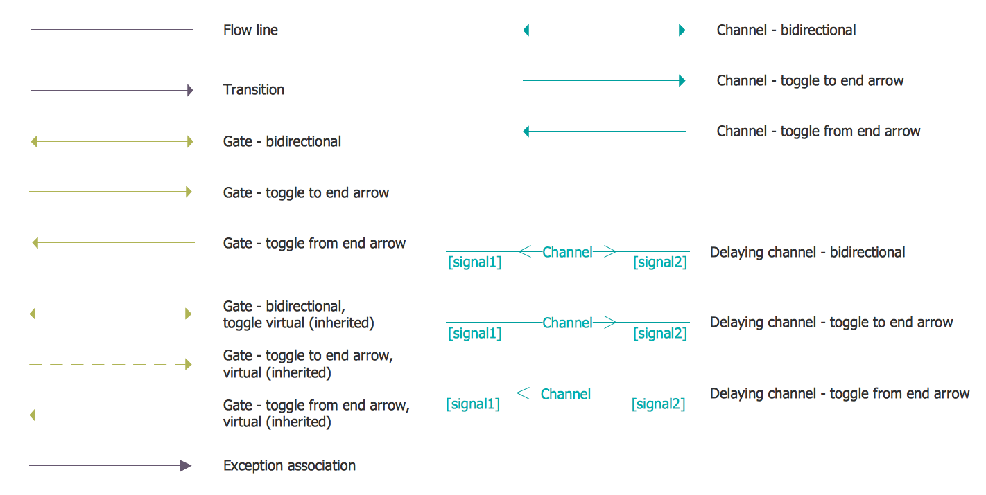
Communication between the components can be performed through different gates that are connected by channels. The mentioned channels are known to be of delayed channel type. That is the reason such communication is usually asynchronous. At the same time, when the delay is set to zero, then such communication becomes synchronous.
The Specification and Description Language (SDL) solution was developed for ConceptDraw DIAGRAM users to simplify their work with an implementation language as well as building the so-called real-time systems which are involved in the parallel processing.
Having a comprehensive selection of connectors and other diagram elements, the Specification and Description Language (SDL) solution allows all the ConceptDraw DIAGRAM users to create the professionally-looking SDL diagrams as well as other SDL-related drawings.
All systems engineers, as well as many other engineers, might find the Specification and Description Language (SDL) solution truly useful in their work.
-
Install this solution Free -
What I need to get started -
Solution Requirements - This solution requires the following products to be installed:
ConceptDraw DIAGRAM v18 - This solution requires the following products to be installed:
-
Compatibility - Sonoma (14), Sonoma (15)
MS Windows 10, 11 - Sonoma (14), Sonoma (15)
-
Support for this Solution -
Helpdesk
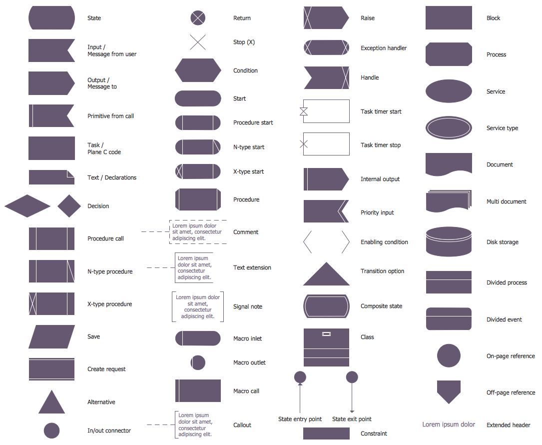
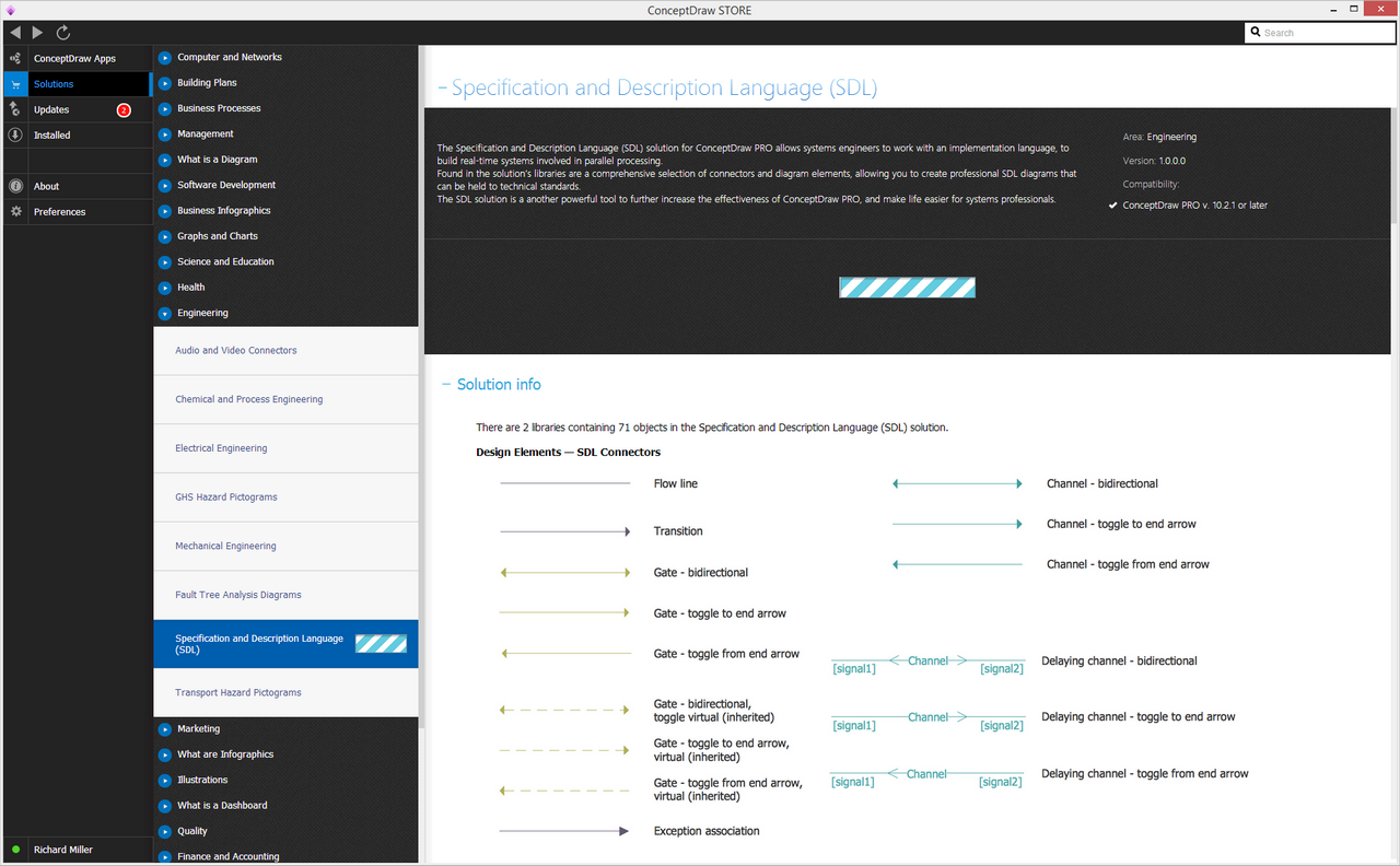
There are 2 libraries containing 71 objects in the Specification and Description Language (SDL) solution.
Design Elements — SDL Connectors
Design Elements — SDL Diagrams
Related News:
Examples
There are a few samples that you see on this page which were created in the ConceptDraw DIAGRAM application by using the Specification and Description Language (SDL) solution. Some of the solution's capabilities as well as the professional results which you can achieve are all demonstrated here on this page.
All source documents are vector graphic documents which are always available for modifying, reviewing and/or converting to many different formats, such as MS PowerPoint, PDF file, MS Visio, and many other graphic ones from the ConceptDraw Solution Park or ConceptDraw STORE. The Specification and Description Language (SDL) solution is available to all ConceptDraw DIAGRAM users to get installed and used while working in the ConceptDraw DIAGRAM diagramming and drawing software.
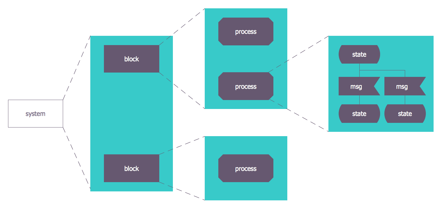
Example 1: SDL Architecture
This diagram was created in ConceptDraw DIAGRAM using the SDL Connectors and SDL Diagrams libraries from the solution. An experienced user spent minutes creating this sample.
This is a generic view of an SDL system, decomposing functional blocks to the lowest level of sub-block. Processes within these sub-blocks are described as finite state machines.
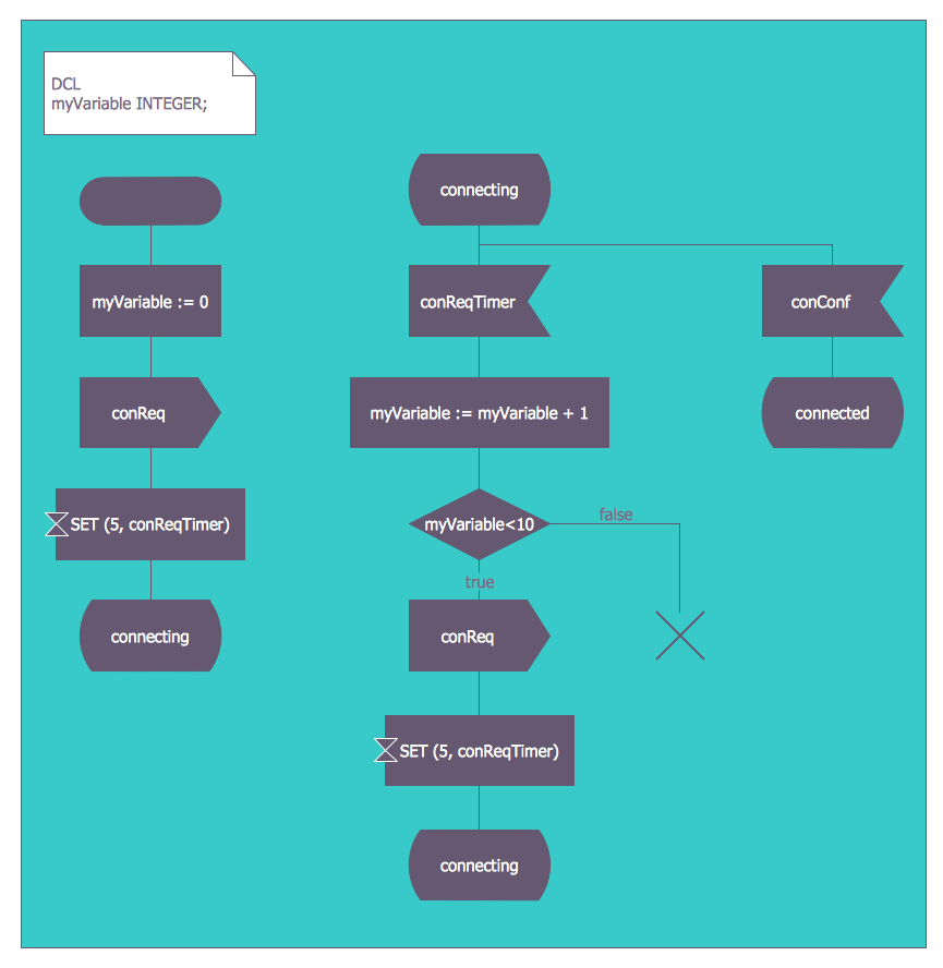
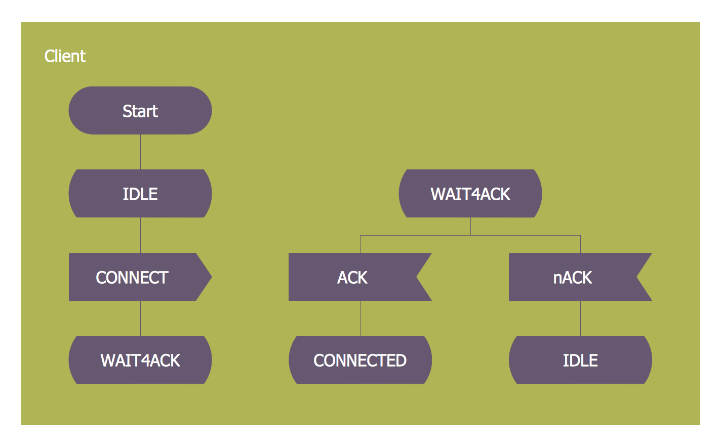
Example 2: SDL Diagram — State Machine
This diagram was created in ConceptDraw DIAGRAM using the SDL Connectors and SDL Diagrams libraries from the solution. An experienced user spent 25 minutes creating this sample.
Finite state machines are inherent to the design of computer programs and sequential logic circuits. They are capable of existing in a variety of 'states', depending on certain conditions - the triggers for these conditions are noted on the diagram.
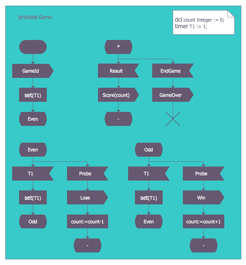
Example 3: SDL Process Game
This diagram was created in ConceptDraw DIAGRAM using the SDL Connectors and SDL Diagrams libraries from the solution. An experienced user spent 10 minutes creating this sample.
You can create logical processes that govern game theory using SDL language. Users working with ConceptDraw DIAGRAM can expect solution graphics and design elements to be held to professional technical standards.
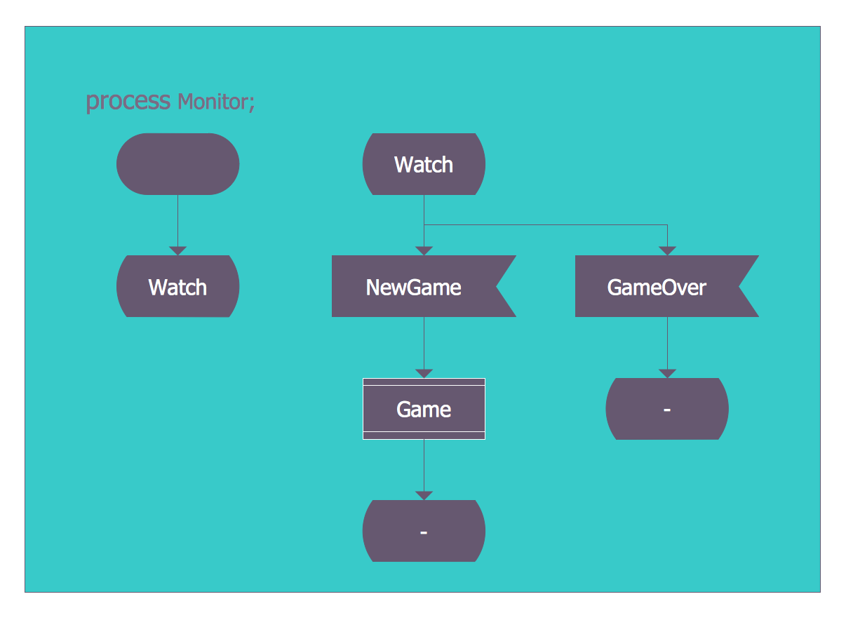
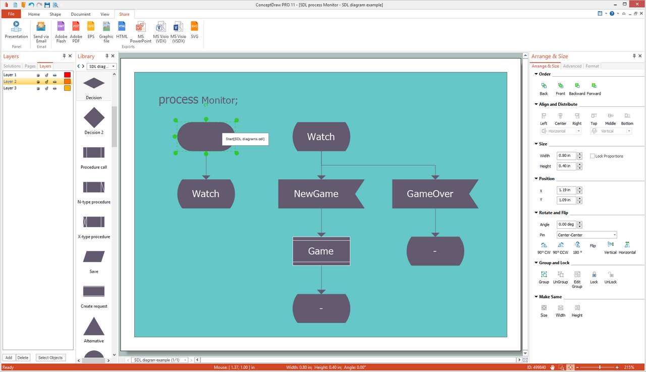
Example 4: SDL Process Monitor
This diagram was created in ConceptDraw DIAGRAM using the SDL Connectors and SDL Diagrams libraries from the solution. An experienced user spent 20 minutes creating this sample.
It's possible to create SDL language process diagrams of any complexity using this solution and ConceptDraw DIAGRAM. Aspects such as color scheme and text style can be formatted to your taste.
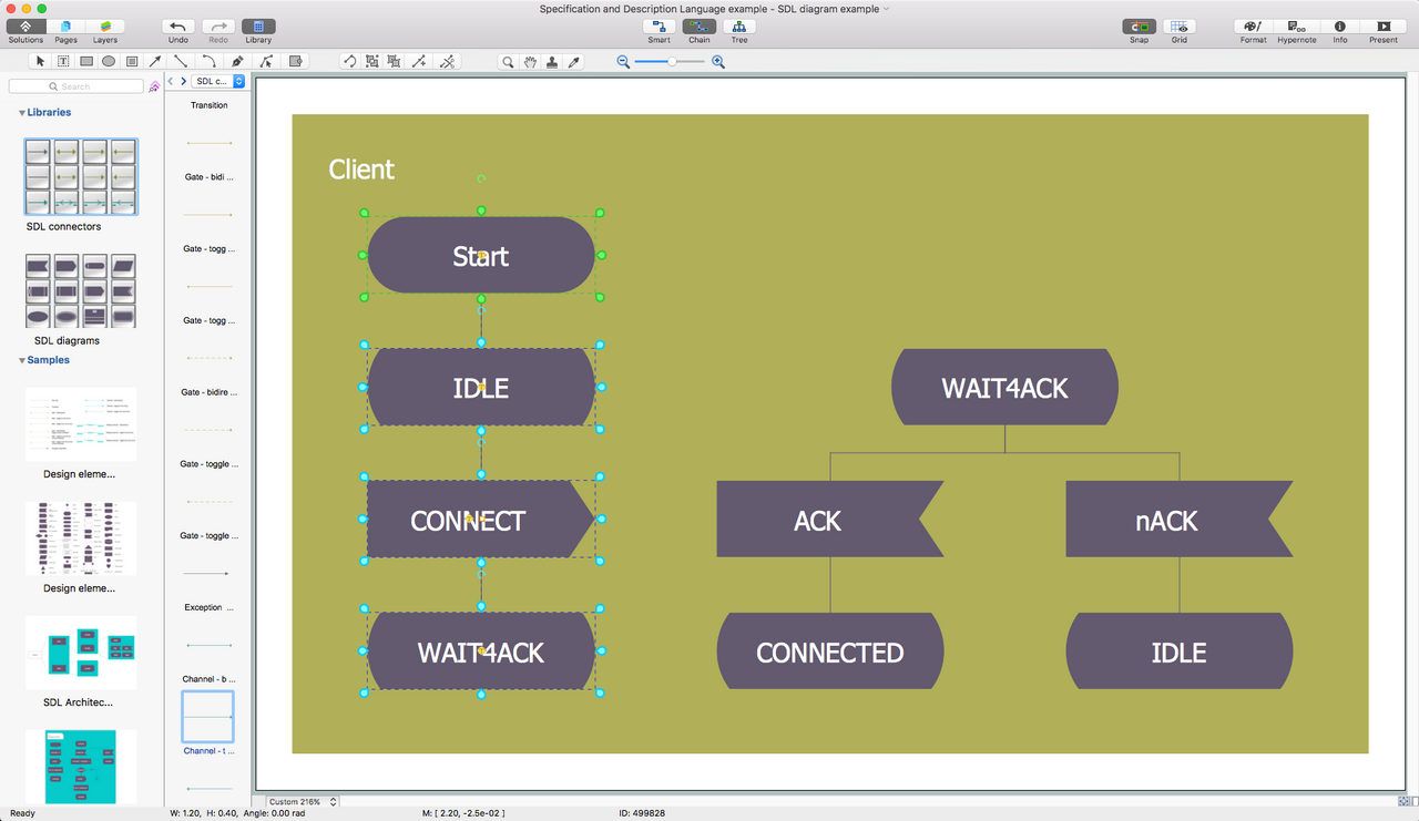
Example 5: Specification and Description Language Example
This diagram was created in ConceptDraw DIAGRAM using the SDL Connectors and SDL Diagrams libraries from the solution. An experienced user spent 15 minutes creating this sample.
SDL allows you to view processes within event-driven systems in isolation, determining their state and the conditions that cause them. ConceptDraw DIAGRAM makes working with Specification and Description Language a simple task.
Inside
What I Need to Get Started
Both ConceptDraw DIAGRAM diagramming and drawing software and the Specification and Description Language (SDL) solution can help creating the illustrations the technical documentation of an engineering projects you need. The Specification and Description Language (SDL) solution can be found in the Industrial Engineering area of ConceptDraw STORE application that can be downloaded from this site. Make sure that both ConceptDraw DIAGRAM and ConceptDraw STORE applications are installed on your computer before you get started.
How to install
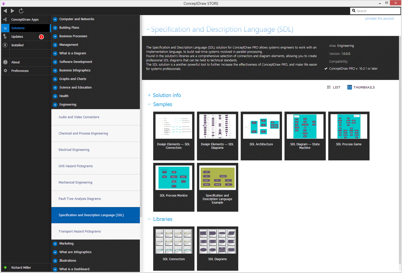
After ConceptDraw STORE and ConceptDraw DIAGRAM are downloaded and installed, you can install the Specification and Description Language (SDL) solution from the ConceptDraw STORE.
Start Using
To make sure that you are doing it all right, use the pre-designed symbols from the stencil libraries from the solution to make your drawings look smart and professional. Also, the pre-made examples from this solution can be used as drafts so your own drawings can be based on them. Using the samples, you can always change their structures, colors and data.
Specification and Description Language (SDL) Diagrams
Specification and Description Language (SDL) was initially devised in the early 1970s with a specific task in mind — to describe systems that switched state rapidly and often. The need for this language was in direct retaliation to the types of system that were rising to prominence during this time, namely telecommunication systems that had become highly complex, with heavy traffic loads and real time demands. This exposed the more rigid programming languages and hardware description languages, that were unable to represent switching systems that required standardization on an international scale.
As telecommunication systems developed, so did SDL, moving from focusing solely on sequential behavior to later adding notation for architectural composition, and finally introducing concepts such as types and inheritance. By this time, SDL was a full-time object oriented language, able to be used when modeling a system graphically (SDL/GR) or textually (SDL/PR).
The basic form of an SDL diagram will involve some or all of the following components:
Structure — the hierarchy of the system, its blocks, processes and procedures.
Communication — signals with optional parameters and channels.
Behavior — processes.
Data — abstract data types.
Inheritance — describing relations and specialization.
Different systems require a different approaches to diagram composition. Here are the three main forms of SDL diagram, and a brief description of their intent:
System architecture/structure
SDL uses a hierarchical structure comprised of 4 levels.
- System
- Blocks
- Processes
- Procedures

Complete overview of a system and it 4 layers, produced with ConceptDraw DIAGRAM
Every SDL diagram is taken as a view of system, be it a simple, single process, or more complex behavior derived from the relationship between a number of blocks. The hierarchy is nested; a system can be decomposed into blocks, each block can be describes as a process, until finally you can see the procedures that make up each process.
The advantages of this style are that a system can seen at any level — information can be shown or hidden, viewed in manageable portions, and paths can be followed individually through all their sub-divisions.
Behavior
When we are describing system behavior using an SDL diagram, we are regarding blocks as finite state machines (FSM). An FSM is ideal form of component for such a diagram, as it is capable of taking on multiple forms, dependent on the type of signal input.

Using ConceptDraw DIAGRAM to take a closer look at finite state machines, with textual information to facilitate understanding
The states an FSM can switch to are clearly and unambiguously shown by the process diagram that is inherent within it. This process diagram describes every input and output of an FSM, the states they change to and from, and the actions they perform depending on which state transition takes place.
Communication
There is rarely direct human contact with a system interface as described by SDL. Transistions and interactions within the system, and with the environment, are governed by signals, which already have a pre-determined cause and effect.

A set of concurrent processes, described using ConceptDraw DIAGRAM
This keeps the blocks, or FSMs, in their finite state and as separate entities to each other — it is not possible for a signal to fundamentally disrupt or change the process within an FSM, only challenge it to make a state transition.
SDL diagrams are ideal candidates for reactive and distributive systems for a number of reasons:
- Formal and standard language, established internationally and through many fields of industry
- Highly testable due to formalism of structure and interface
- Graphical and symbol based, allowing for full interpretation of detail
- Portable, scalable and open, acting independently of operating systems, processors and distribution methods.
- Recyclable, able to apply the same processes to many different scenarios
Specification and Description Language began life a tool for telecommunication software engineers, and it remains highly tried in that field today. Indeed, Nokia have developed their own variant named TNSDL to be used exclusively with their systems. At the same time, the user base has widened, and you can find examples of their use in automotive, aviation, and medical industries.
With a track record of producing technical, standardized solutions, CS Odessa have once again furthered the abilities of their diagramming software, ConceptDraw DIAGRAM, by releasing the Specification and Description Language solution.
The solution contains one library, with all language notation professionally drawn as vector stencil graphics. ConceptDraw DIAGRAM 's 'intelligent connector' technology allows you to be dynamic with your design, with connector lines between blocks automatically plotting an unencumbered path around the page as elements are added and relocated. As is usually the case with CS Odessa solutions, the SDL solution also contains a set of pre-designed templates and samples, to provide inspiration and to show the level of hierarchical detail that is possible.
For system engineers, the Specification and Description Language solution is the only resource necessary to create clear and focused professionally drawn SDL diagrams.