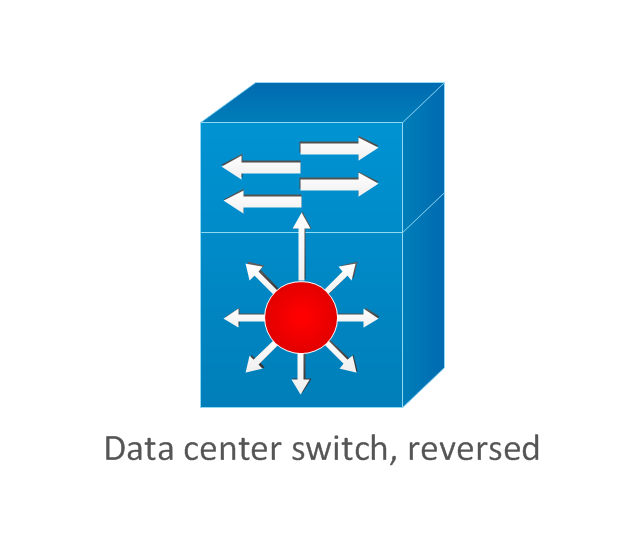
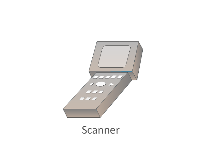
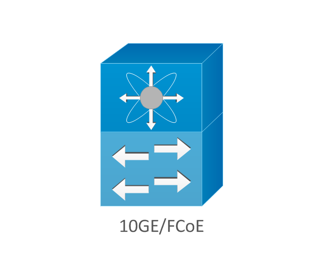
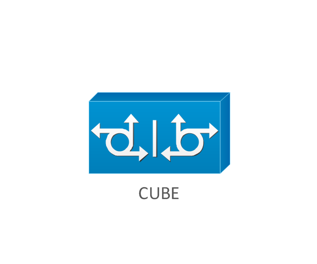
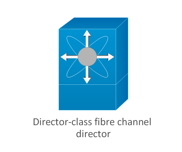
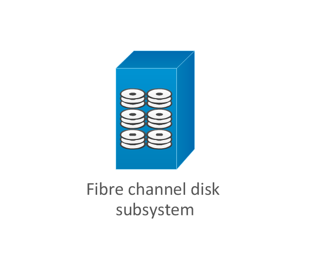
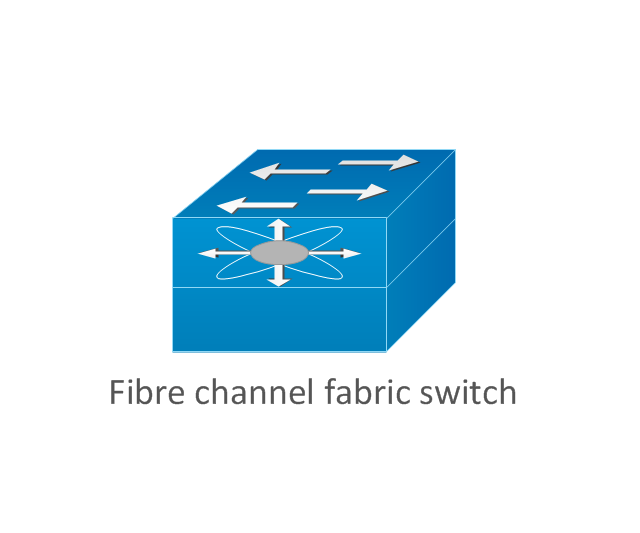
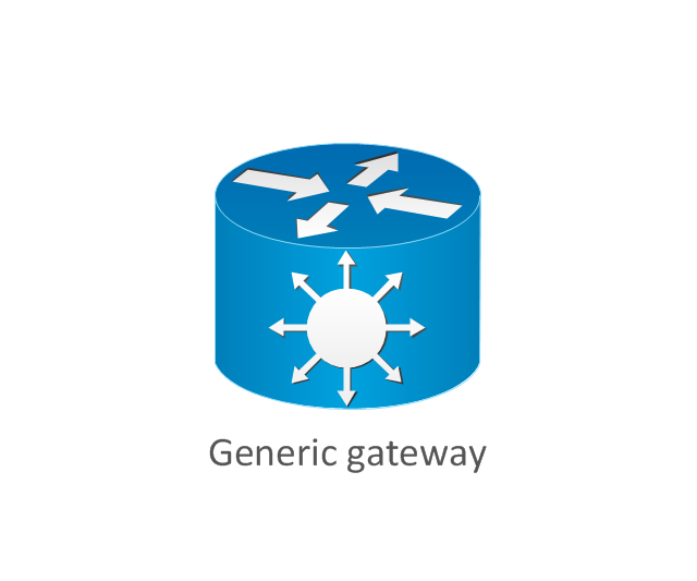
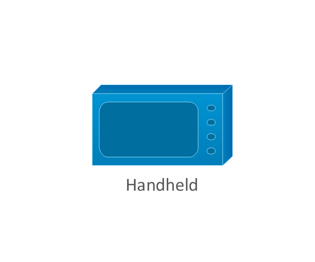
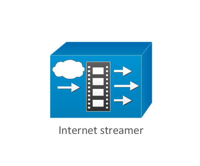
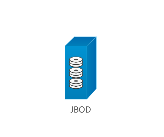
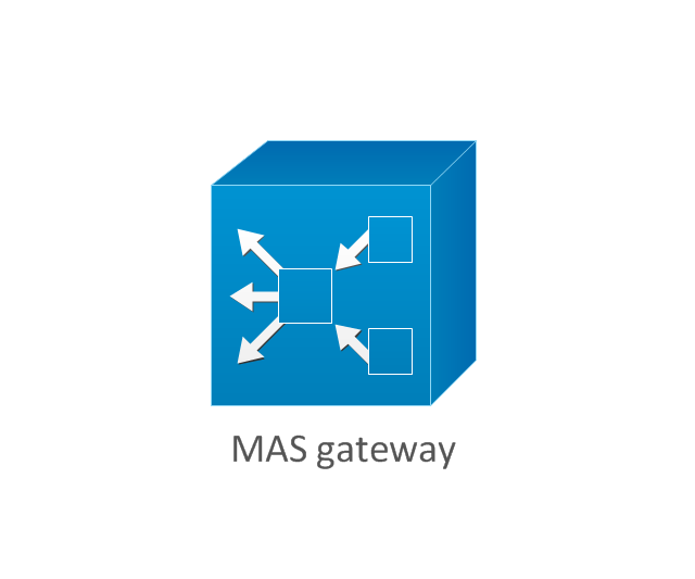
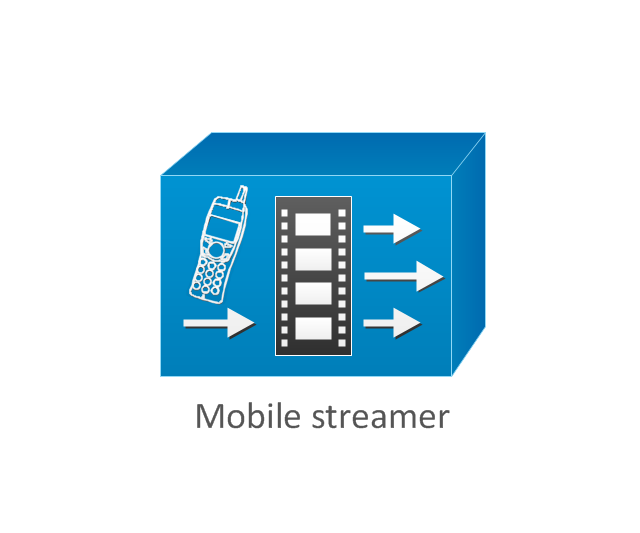
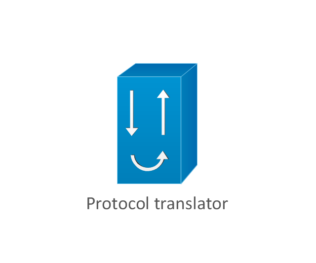
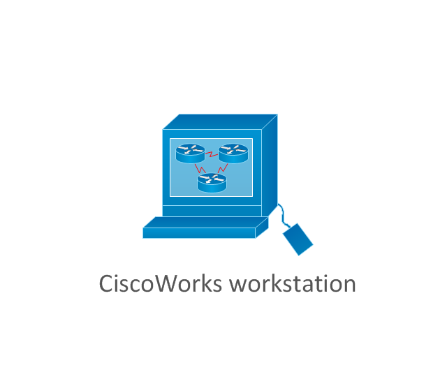
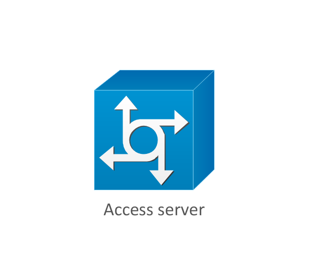
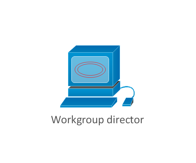
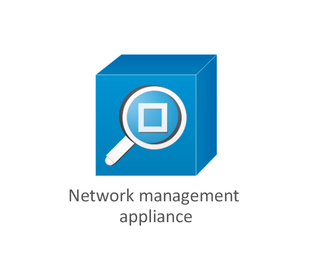
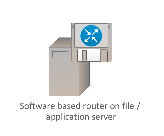
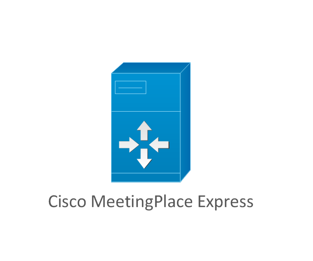
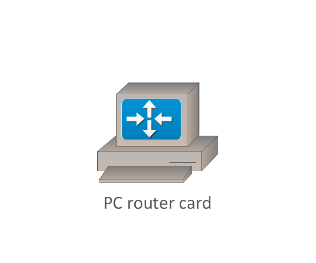
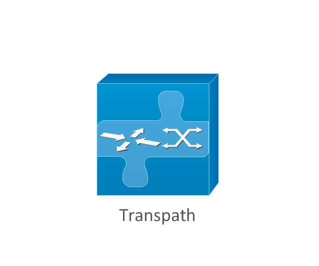
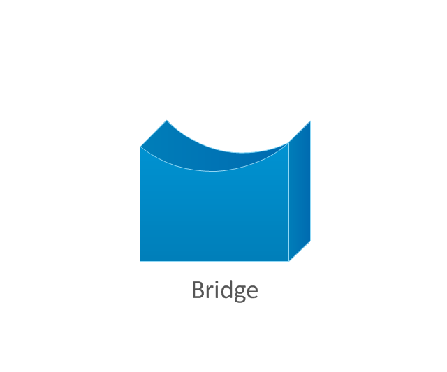
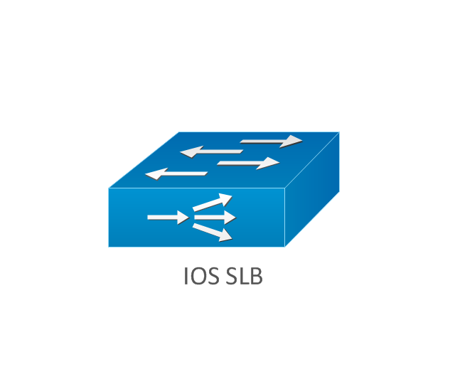
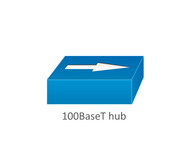
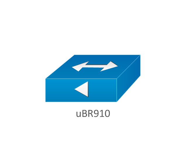
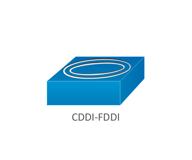
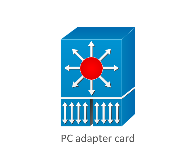
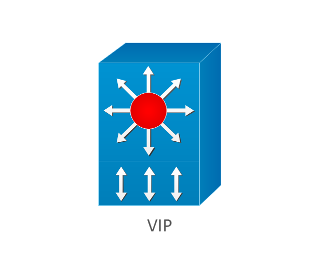
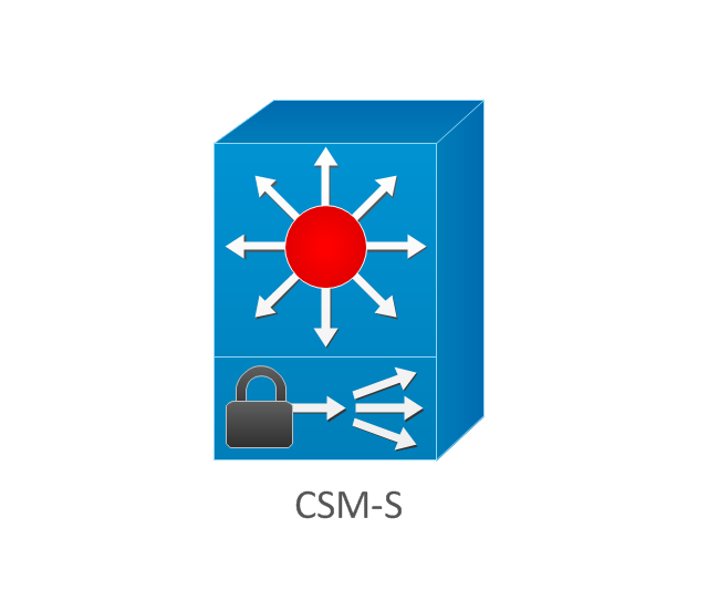
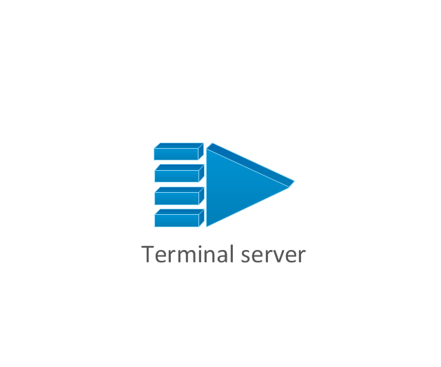
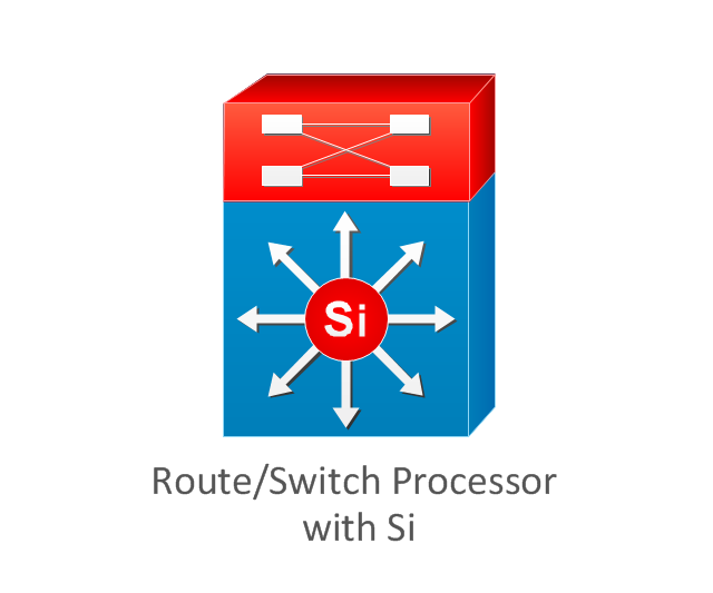
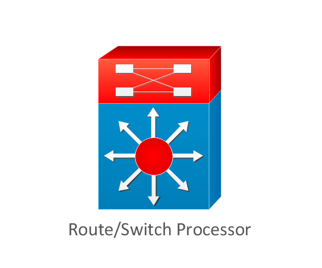
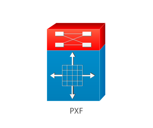
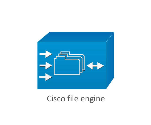
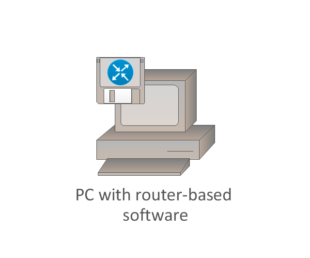
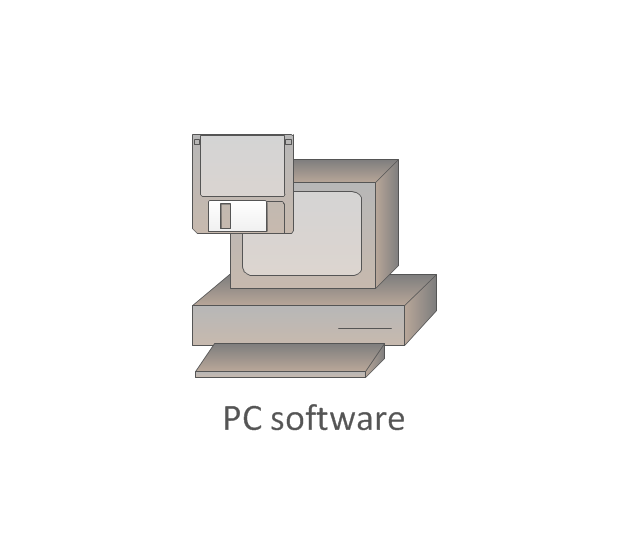
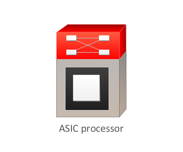
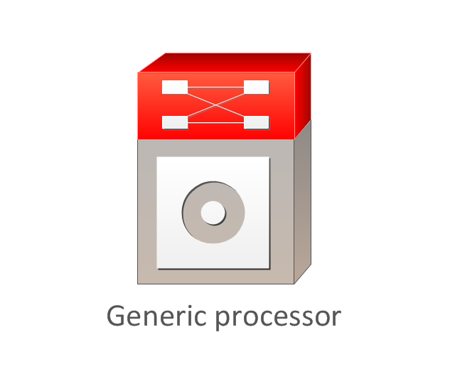
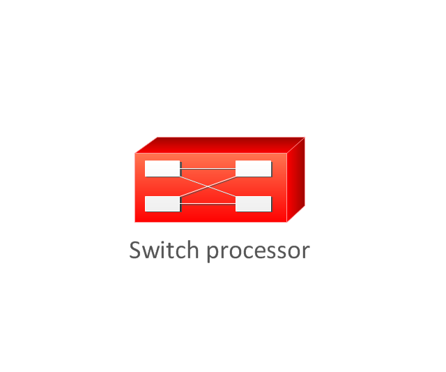
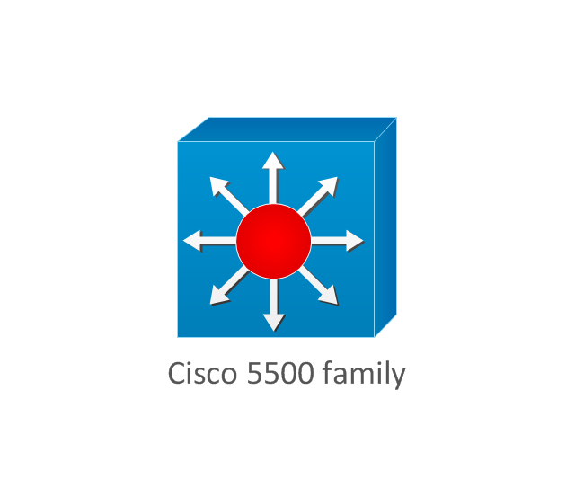
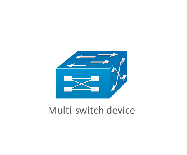
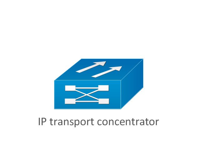
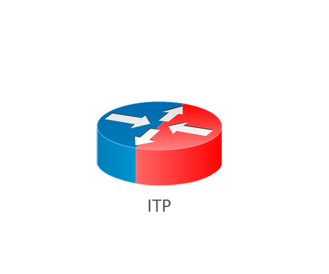
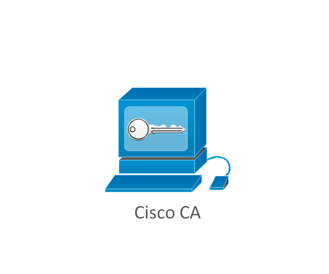
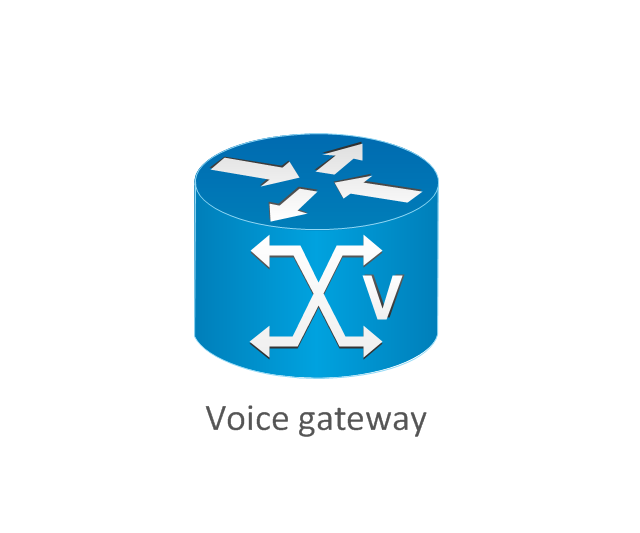
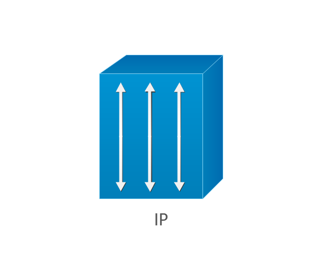
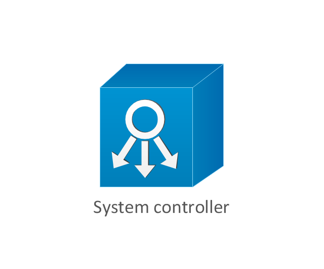
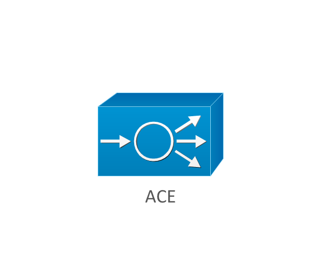
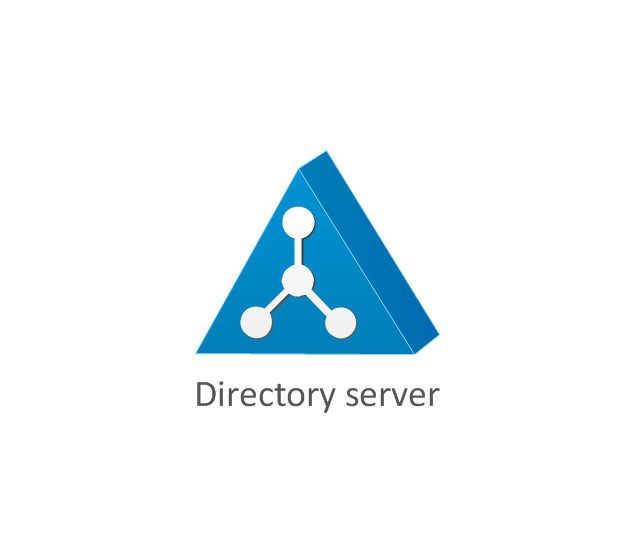
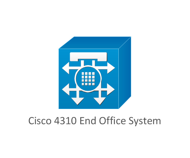
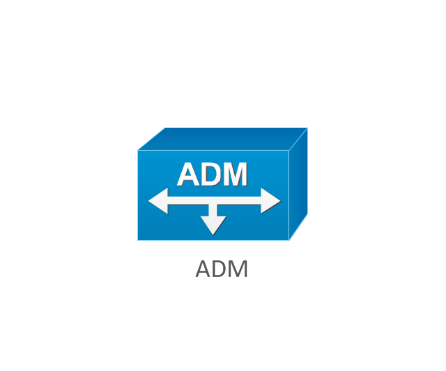
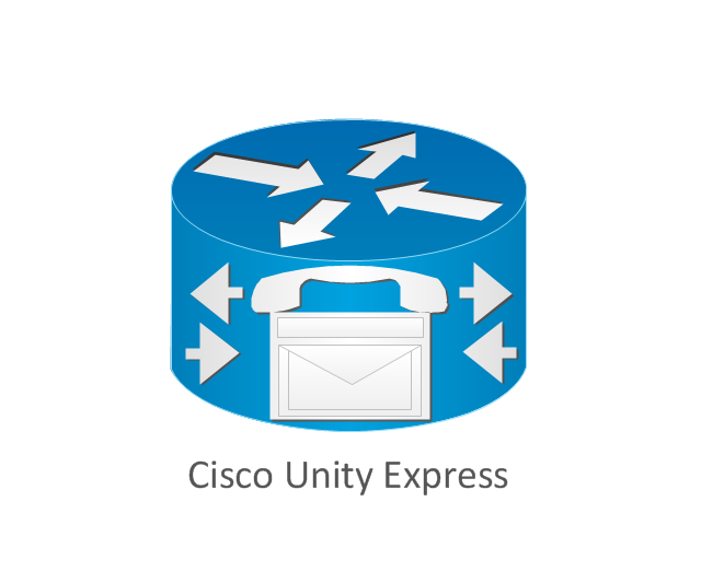
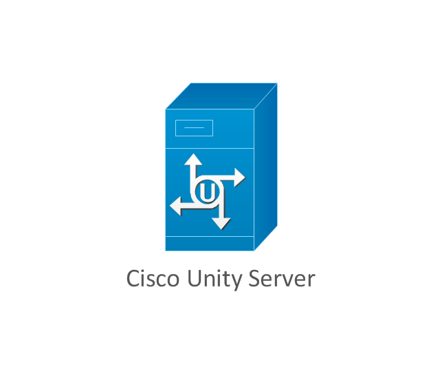
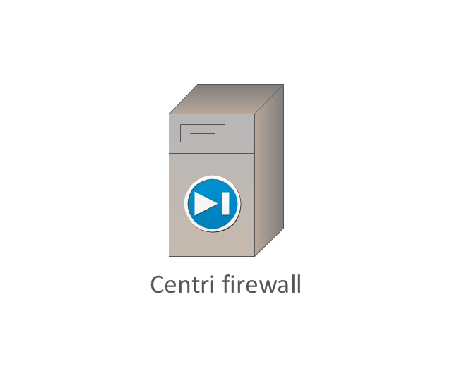
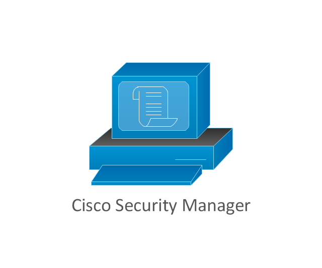
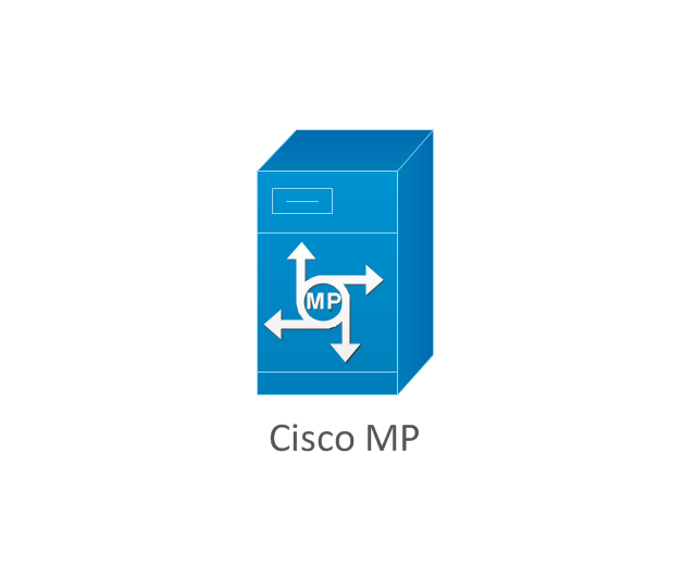
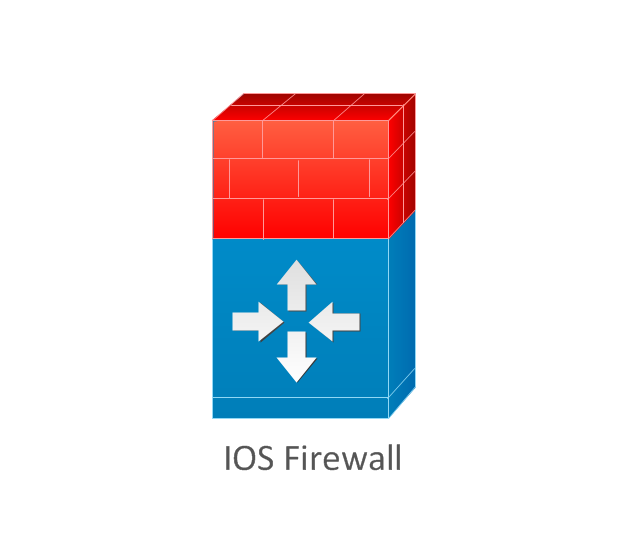
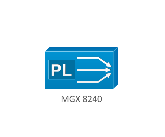
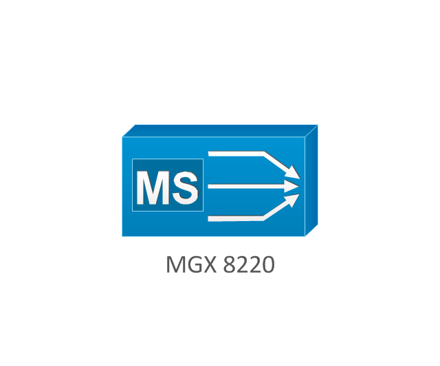
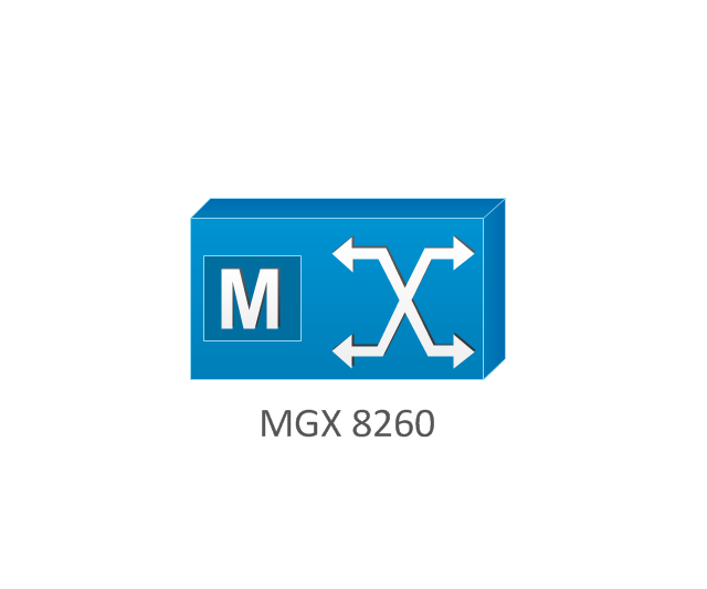
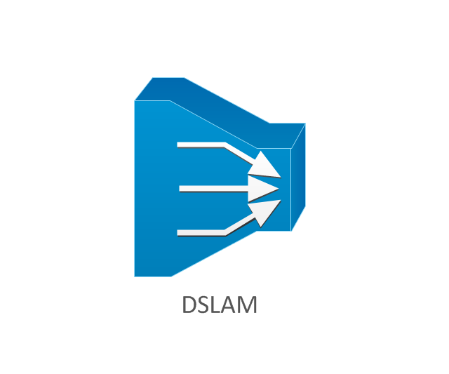
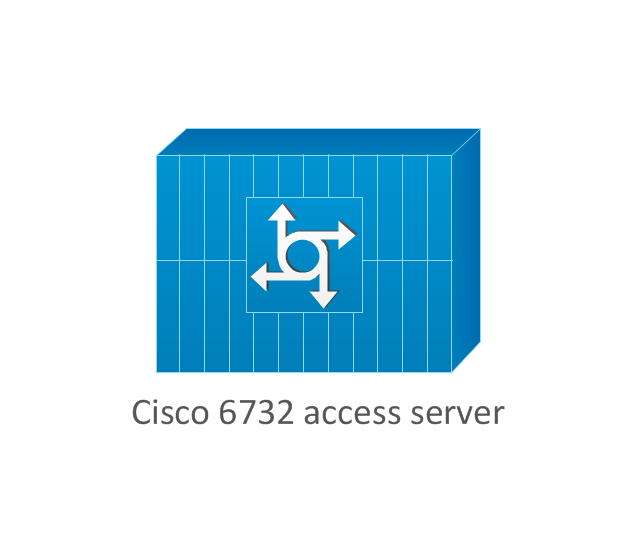
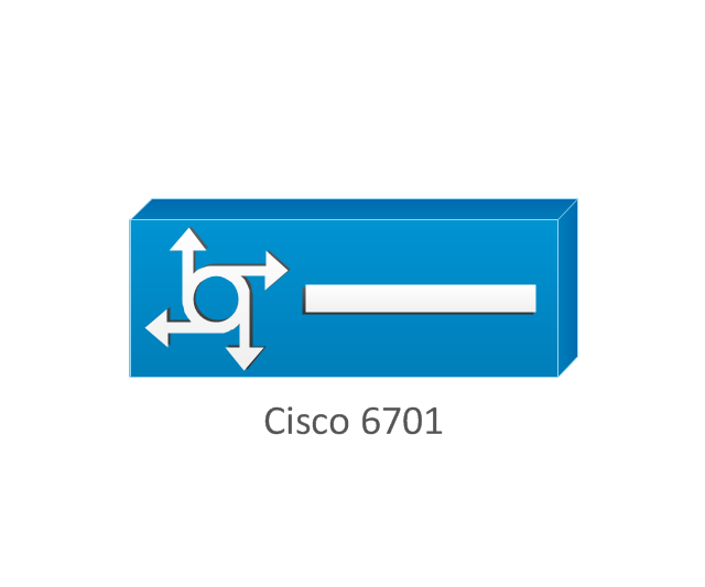
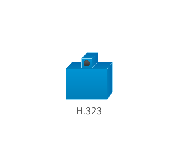
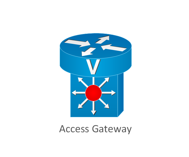
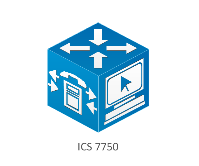
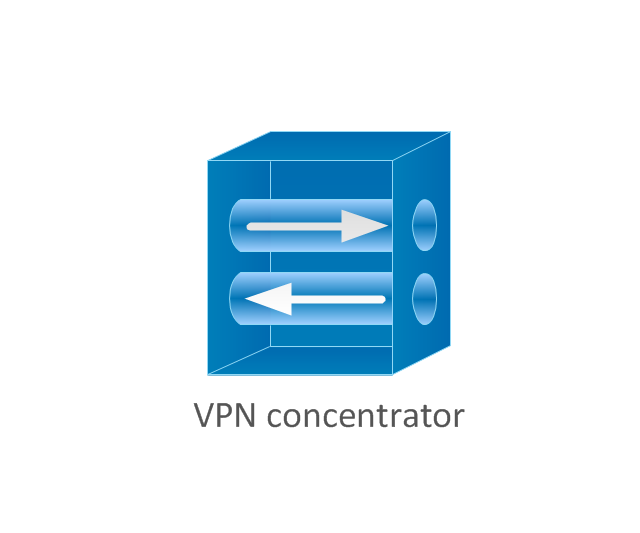
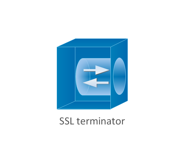
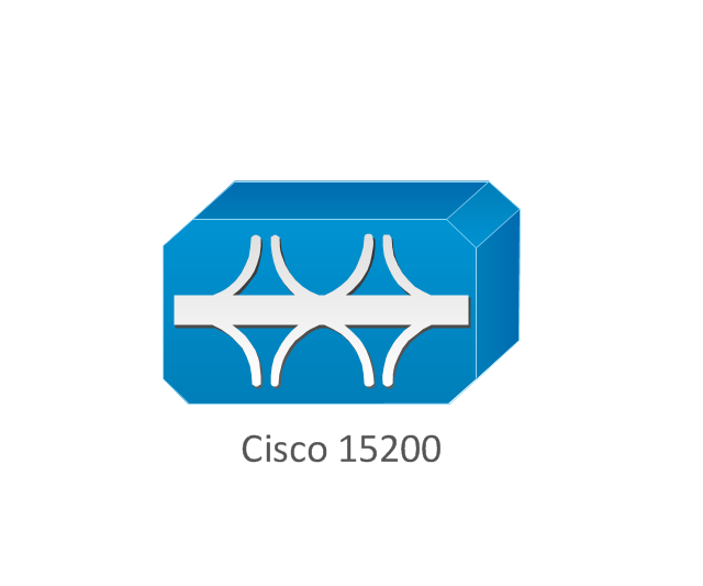
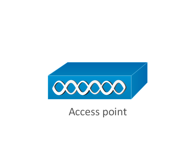
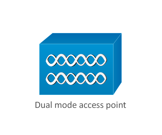
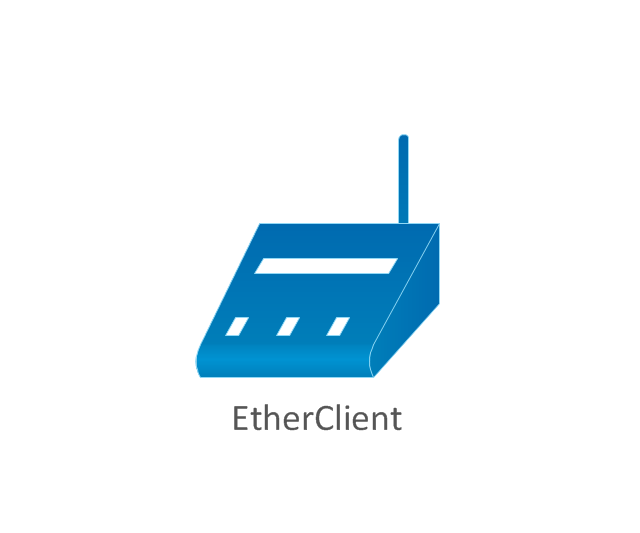
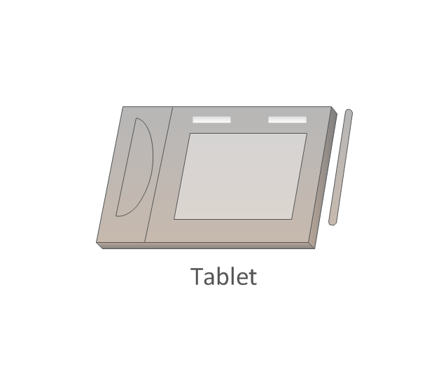
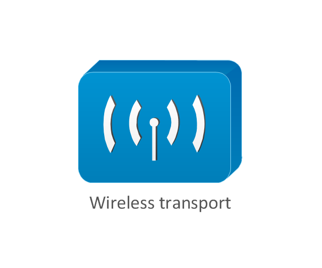
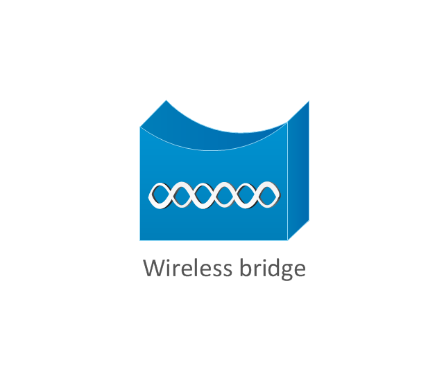
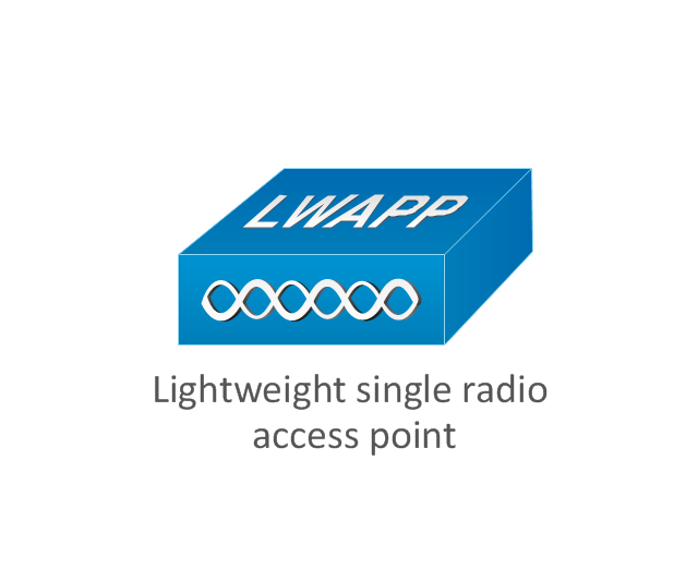
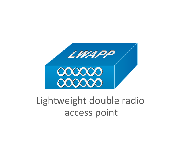
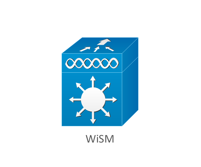
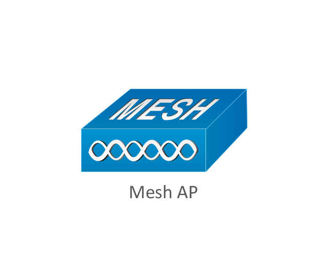
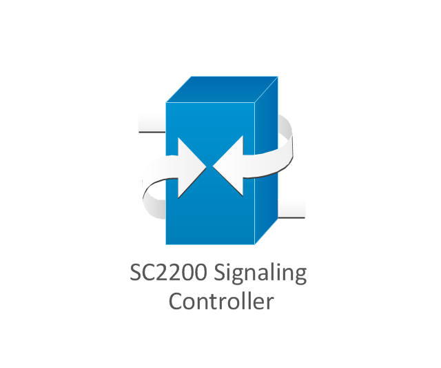
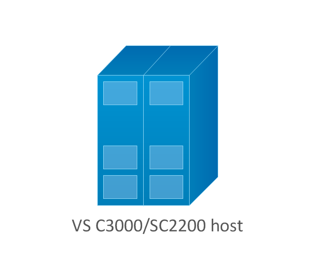
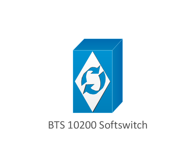
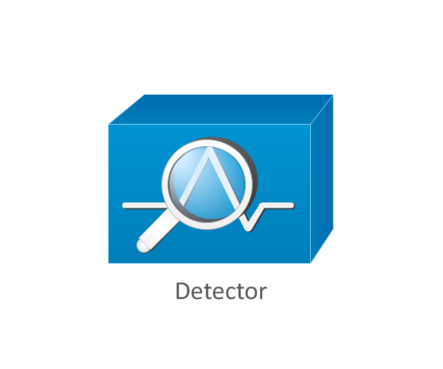
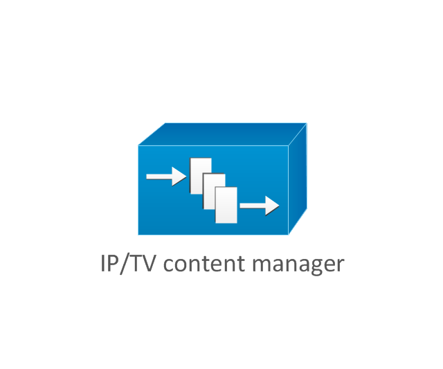
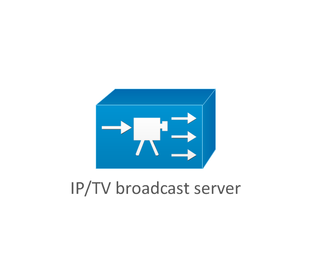
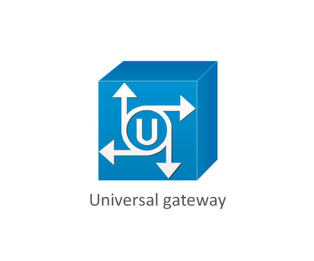
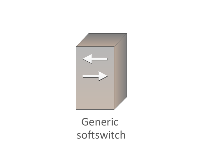
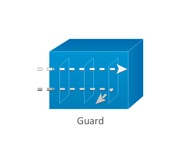
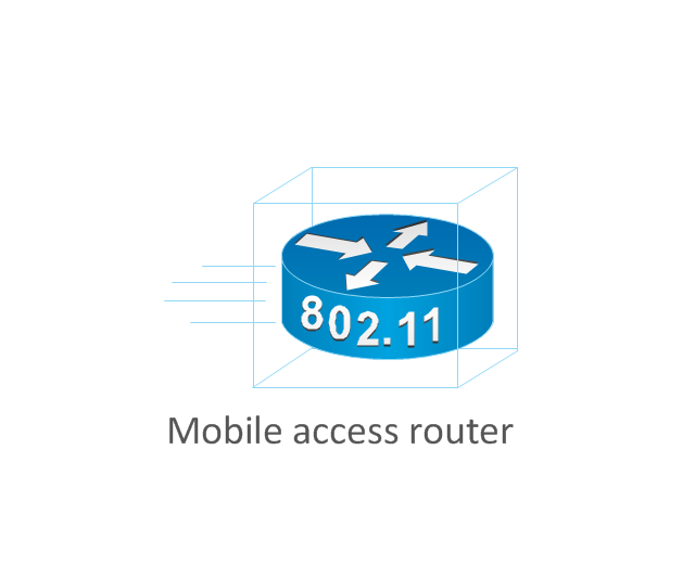
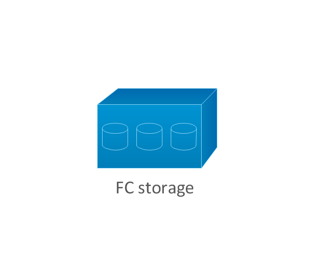
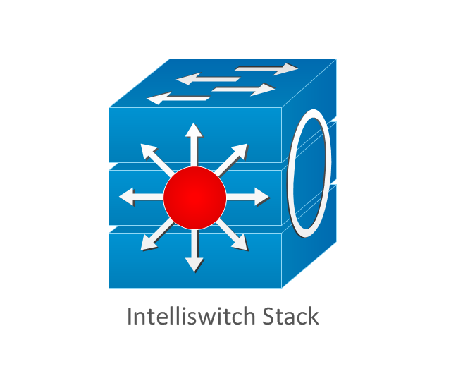
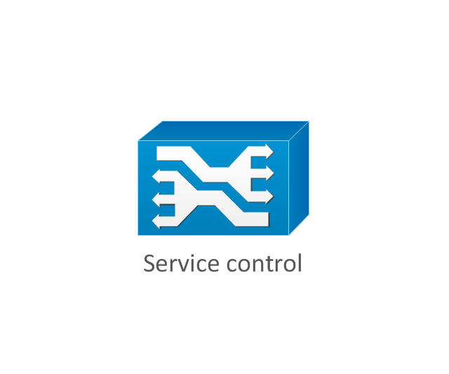
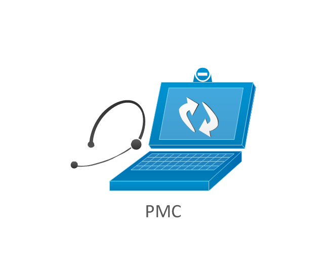
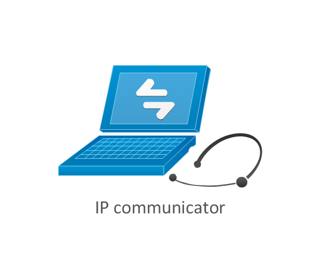
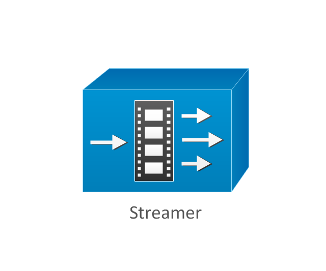
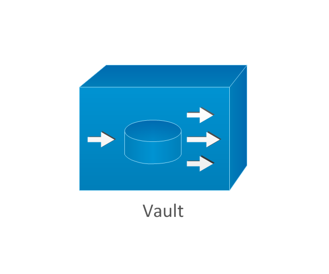
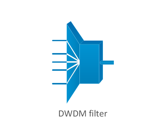
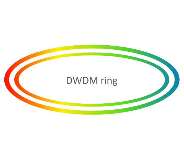
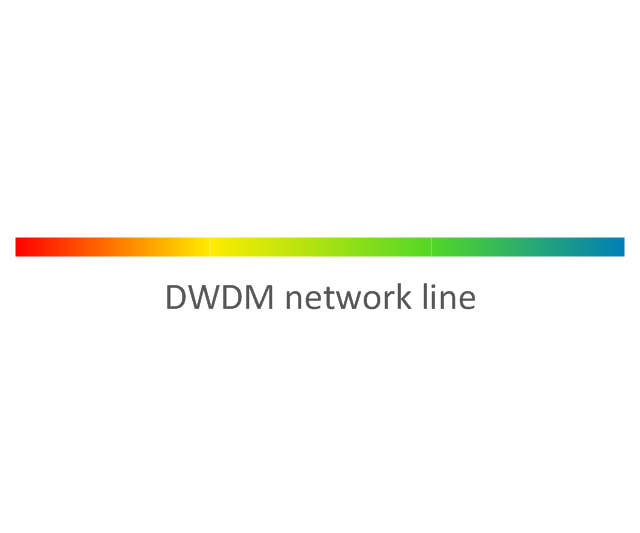
The vector stencils library "Cisco products additional" contains 141 symbols of computer network devices and equipment for drawing Cisco network diagrams.
The symbols example "Cisco products additional - Vector stencils library" was created using the ConceptDraw PRO diagramming and vector drawing software extended with the Cisco Network Diagrams solution from the Computer and Networks area of ConceptDraw Solution Park.
www.conceptdraw.com/ solution-park/ computer-networks-cisco
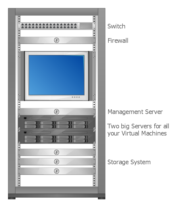
This rack diagram example was drawn on the base of picture illustrating the article "Virtualization in general, for technicans and business people" from the Banym's Blog by Dominik Zajac. [banym.de/ virtualization/ virtualization-in-general-for-technicans-and-business-people]
"Virtualization, in computing, refers to the act of creating a virtual (rather than actual) version of something, including but not limited to a virtual computer hardware platform, operating system (OS), storage device, or computer network resources." [Virtualization. Wikipedia]
"With the CPUs we have today you can virtualize up to 10 – 12 old servers to one new big machine with for example 2 x 6 core CPUs and a lot of memory. In this case you see what potential this technology has. Turn off 10 servers and run it on just one machine. That’s not the way I would do Virtualization. It’s nice to save energy but what happens if we have a problem with our one new big server? The complete organization can not work without ERP, EMail etc. and because of this we need a cluster.
Such a cluster configuration looks something like this: (rack diagram example).
Two big servers, a storage subsystem and a smaller management server. If you compare now the old configuration with the new one you can see there will be still made some points for energy efficiency. That’s not the only benefit you should have in focus, for the mature Virtualization solutions like VMware or Citrix/ XEN exist a big number of tools and documentation to make the life easier for administrators and system managers. This safes time and brings better reaction times for your IT." [banym.de/ virtualization/ virtualization-in-general-for-technicans-and-business-people]
The rack diagram example "Virtualized computer center" was created using the ConceptDraw PRO diagramming and vector drawing software extended with the Rack Diagrams solution from the Computer and Networks area of ConceptDraw Solution Park.
The vector stencils library "Computer network" contains 51 symbols of computer network devices and equipment for drawing computer network diagrams.
"Network Mapping Software.
A number of software tools exist to design computer network diagrams / or generate visual maps of networks, servers, storage, services, data centers, and other peripherals. Broadly, there are two types of software tools - those that help create diagrams manually and those that generate them using automated / semi-automated approaches.
Type of Software.
(1) Manual - allows users to design and draw logical and physical topology diagrams by manually placing icons and connections.
(2) Automated - generate topology diagrams / maps by traversing the network and automatically discovering resident devices or by importing network data." [Comparison of network diagram software. Wikipedia]
ConceptDraw PRO is the software for manual design of computer network diagrams. The solutions of the Computer and Networks area in ConceptDraw Solution Park extend ConceptDraw PRO with vector stencils libraries, templates and examples for creating the computer network diagrams.
The symbols example "Computer network - Vector stencils library" was created using the ConceptDraw PRO diagramming and vector drawing software extended with the Computer and Networks solution from the Computer and Networks area of ConceptDraw Solution Park.
www.conceptdraw.com/ solution-park/ computer-and-networks
The vector stencils library "Application" contains 40 icons of software applications.
Use it to design your computer and telecom illustrations and infographics with ConceptDraw PRO diagramming and vector drawing software.
The vector stencils library "Application" is included in the Computers and Communications solution from the Illustration area of ConceptDraw Solution Park.
Use it to design your computer and telecom illustrations and infographics with ConceptDraw PRO diagramming and vector drawing software.
The vector stencils library "Application" is included in the Computers and Communications solution from the Illustration area of ConceptDraw Solution Park.
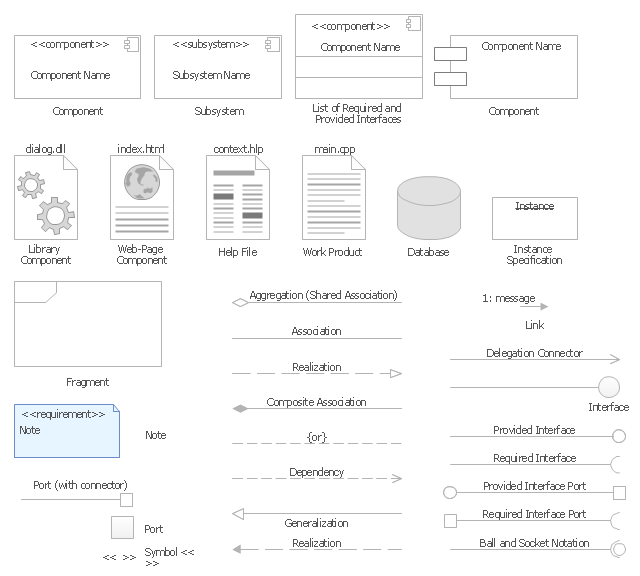
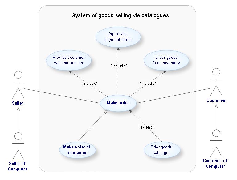
The vector stencils library "UML component diagrams" contains 36 symbols for the ConceptDraw PRO diagramming and vector drawing software.
"In the Unified Modeling Language, a component diagram depicts how components are wired together to form larger components and or software systems. They are used to illustrate the structure of arbitrarily complex systems. ...
Symbols.
This may have a visual stereotype in the top right of the rectangle of a small rectangle with two even smaller rectangles jutting out on the left.
The lollipop, a small circle on a stick represents an implemented or provided interface. The socket symbol is a semicircle on a stick that can fit around the lollipop. This socket is a dependency or needed interface." [Component diagram. Wikipedia]
The example "Design elements - UML component diagrams" is included in the Rapid UML solution from the Software Development area of ConceptDraw Solution Park.
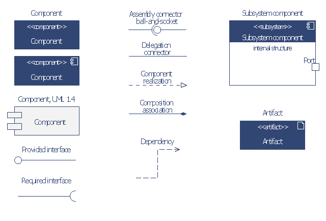
The vector stencils library "Bank UML component diagram" contains 13 shapes for drawing UML component diagrams.
Use it for object-oriented modeling of your bank information system.
"A component is something required to execute a stereotype function. Examples of stereotypes in components include executables, documents, database tables, files, and library files.
Components are wired together by using an assembly connector to connect the required interface of one component with the provided interface of another component. This illustrates the service consumer - service provider relationship between the two components. ...
When using a component diagram to show the internal structure of a component, the provided and required interfaces of the encompassing component can delegate to the corresponding interfaces of the contained components. ...
Symbols.
This may have a visual stereotype in the top right of the rectangle of a small rectangle with two even smaller rectangles jutting out on the left.
The lollipop, a small circle on a stick represents an implemented or provided interface. The socket symbol is a semicircle on a stick that can fit around the lollipop. This socket is a dependency or needed interface." [Component diagram. Wikipedia]
This example of UML component diagram symbols for the ConceptDraw PRO diagramming and vector drawing software is included in the ATM UML Diagrams solution from the Software Development area of ConceptDraw Solution Park.
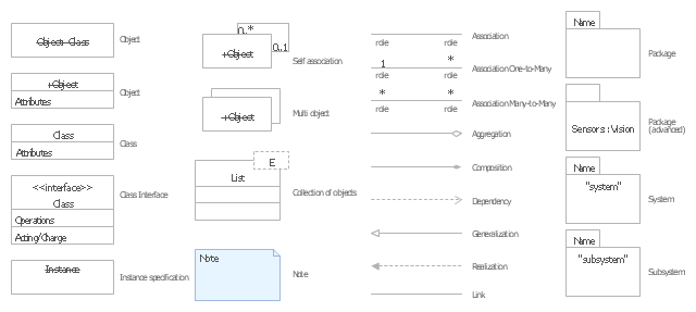
The vector stencils library "UML object diagrams" contains 26 symbols for the ConceptDraw PRO diagramming and vector drawing software.
"Each object and link on an object diagram is represented by an InstanceSpecification. This can show an object's classifier (e.g. an abstract or concrete class) and instance name, as well as attributes and other structural features using slots. Each slot corresponds to a single attribute or feature, and may include a value for that entity.
The name on an instance specification optionally shows an instance name, a ':' separator, and optionally one or more classifier names separated by commas. The contents of slots, if any, are included below the names, in a separate attribute compartment. A link is shown as a solid line, and represents an instance of an association. ...
If you are using a UML modeling tool, you will typically draw object diagrams using some other diagram type, such as on a class diagram. An object instance may be called an instance specification or just an instance. A link between instances is generally referred to as a link. Other UML entities, such as an aggregation or composition symbol (a diamond) may also appear on an object diagram." [Object diagram. Wikipedia]
The example "Design elements - UML object diagrams" is included in the Rapid UML solution from the Software Development area of ConceptDraw Solution Park.
ConceptDraw PRO UML Diagrams with ConceptDraw PRO
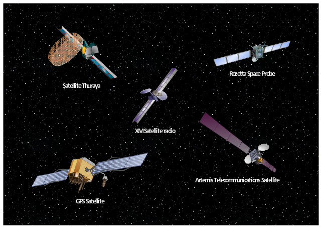
ConceptDraw PRO is a great UML modeling and design tool that enables you to quickly and easily generate all types of UML diagrams. ConceptDraw PRO offers a large collection of industry-standard UML object libraries for all types of UML diagrams.Use vector clipart library Aerospace to illustrate your documents, infographics, presentations and websites with images of satellites, space vehicles and objects using ConceptDraw PRO diagramming and vector drawing software.
"In the context of spaceflight, a satellite is an artificial object which has been intentionally placed into orbit.
Some satellites, notably space stations, have been launched in parts and assembled in orbit. A few hundred satellites are currently operational, whereas thousands of unused satellites and satellite fragments orbit the Earth as space debris. A few space probes have been placed into orbit around other bodies and become artificial satellites to the Moon, Mercury, Venus, Mars, Jupiter, Saturn, Vesta, Eros, and the Sun.
Common types include military and civilian Earth observation satellites, communications satellites, navigation satellites, weather satellites, and research satellites. Space stations and human spacecraft in orbit are also satellites. Satellite orbits ... include low Earth orbit, polar orbit, and geostationary orbit.
Satellites are propelled by rockets to their orbits.
Satellites are usually semi-independent computer-controlled systems. Satellite subsystems attend many tasks, such as power generation, thermal control, telemetry, attitude control and orbit control." [Satellite. Wikipedia]
The vector stencils library Aerospace is included in the Aerospace and Transport solution from Illustration area of ConceptDraw Solution Park.
The vector stencils library "Network layout floorplan" contain 34 symbol icons for drawing computer network floor plans, communication equipment layouts, and structured cabling diagrams.
"Structured cabling is building or campus telecommunications cabling infrastructure that consists of a number of standardized smaller elements (hence structured) called subsystems. ...
Structured cabling design and installation is governed by a set of standards that specify wiring data centers, offices, and apartment buildings for data or voice communications using various kinds of cable, most commonly category 5e (CAT-5e), category 6 (CAT-6), and fibre optic cabling and modular connectors. These standards define how to lay the cabling in various topologies in order to meet the needs of the customer, typically using a central patch panel (which is normally 19 inch rack-mounted), from where each modular connection can be used as needed. Each outlet is then patched into a network switch (normally also rack-mounted) for network use or into an IP or PBX (private branch exchange) telephone system patch panel." [Structured cabling. Wikipedia]
The design elements example "Network layout floorplan - Vector stencils library" was created using the ConceptDraw PRO diagramming and vector drawing software extended with the Network Layout Floor Plans solution from the Computer and Networks area of ConceptDraw Solution Park.
- Fibre channel disk subsystem
- Design elements - Rapid UML solution (component diagram ...
- Satellites | Aerospace - Design Elements | Using Both Wired and ...
- Computer network - Vector stencils library
- Apple machines - Vector stencils library
- Design elements - UML component diagrams
- Cisco Products Additional. Cisco icons, shapes, stencils and symbols
- Internet Connectivity. Computer and Network Examples | 3D Column ...
- Ring Network Topology | Cisco Products Additional. Cisco icons ...
- Telecommunication Network Diagrams | Network Diagram ...
- Cisco products additional - Vector stencils library | Wireless ...
- Cable TV - Vector stencils library | Design elements - Cable TV ...
- Cisco Network Design. Cisco icons, shapes, stencils, symbols and ...
- Cisco Products Additional. Cisco icons, shapes, stencils and ...
- Bus Network Topology
- Cisco products additional - Vector stencils library | Cisco Products ...
- iPhone OS (iOS) graphic user interface (GUI) - Standby mode ...
- Event-driven Process Chain Diagrams EPC | Entity-Relationship ...
- Cisco products additional - Vector stencils library | Logical symbols ...
- Mobile satellite TV network diagram | Building Networks ...
-cisco-products-additional---vector-stencils-library.png--diagram-flowchart-example.png)
-cisco-products-additional---vector-stencils-library.png--diagram-flowchart-example.png)
-cisco-products-additional---vector-stencils-library.png--diagram-flowchart-example.png)
-cisco-products-additional---vector-stencils-library.png--diagram-flowchart-example.png)
-cisco-products-additional---vector-stencils-library.png--diagram-flowchart-example.png)
-cisco-products-additional---vector-stencils-library.png--diagram-flowchart-example.png)
-cisco-products-additional---vector-stencils-library.png--diagram-flowchart-example.png)
-cisco-products-additional---vector-stencils-library.png--diagram-flowchart-example.png)
-cisco-products-additional---vector-stencils-library.png--diagram-flowchart-example.png)
-cisco-products-additional---vector-stencils-library.png--diagram-flowchart-example.png)
-cisco-products-additional---vector-stencils-library.png--diagram-flowchart-example.png)
-cisco-products-additional---vector-stencils-library.png--diagram-flowchart-example.png)
-cisco-products-additional---vector-stencils-library.png--diagram-flowchart-example.png)
-cisco-products-additional---vector-stencils-library.png--diagram-flowchart-example.png)
-cisco-products-additional---vector-stencils-library.png--diagram-flowchart-example.png)
