HelpDesk
How to Create an Electrical Diagram
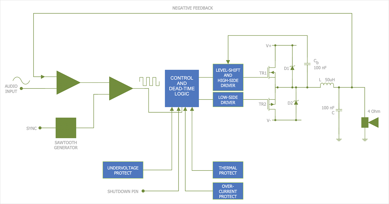
There are many different electric circuit symbols that can be used in a circuit diagram. Knowing how to read circuit diagrams is a useful skill not only for professionals but for any person who can start creating his own small home electronic projects. The circuit diagram shows the scheme of a location of components and connections of the electrical circuit using a set of standard symbols. It can be used for graphical documentation of electrical circuit components. The ability to create electrical diagrams and schematic using ConceptDraw DIAGRAM is delivered by the Electrical Engineering solution. The solution supplied with samples, templates, and libraries of design elements for drawing electrical schematics, digital and analog logic, circuit and wiring schematics and diagrams, power systems diagrams, maintenance and repair diagrams for electronics and electrical engineering.How To use Switches in Network Diagram
Special libraries of highly detailed, accurate shapes and computer graphics, servers, hubs, switches, printers, mainframes, face plates, routers etc.
Basic Network Diagram
The Basic Network Diagram is an easy and effective way to design and document a simple network, it lets to represent visually and logically how the different network devices and computer equipment can be installed to meet the main business needs. ConceptDraw DIAGRAM software supplied with Computer Network Diagrams solution from the Computer and Networks area of ConceptDraw Solution Park is a perfect tool for drawing the Basic Computer Network diagrams, designs, schematics, and maps, network architectures, topologies, and layouts. Numerous vector libraries of network symbols, icons and components are incredibly helpful for IT and telecom engineers, stakeholders and end-users when designing Basic Network Diagrams, Common Network Diagrams, Common Network Topologies, 10Base-T Star Network Topologies, Bus Topology Diagrams, Communication Network Diagrams, System Designs, Regional Cable Head-End Diagrams, etc. Collection of predesigned samples and templates included to Computer Network Diagrams solution also greatly extends the capabilities of ConceptDraw DIAGRAM users.
This cafe electrical floor plan sample shows the outlet and switch layout.
"An electrical drawing, is a type of technical drawing that shows information about power, lighting, and communication for an engineering or architectural project. Any electrical working drawing consists of "lines, symbols, dimensions, and notations to accurately convey an engineering's design to the workers, who install the electrical system on the job".
A complete set of working drawings for the average electrical system in large projects usually consists of:
(1) A plot plan showing the building's location and outside electrical wiring.
(2) Floor plans showing the location of electrical systems on every floor.
(3) Power-riser diagrams showing panel boards.
(4) Control wiring diagrams.
(5) Schedules and other information in combination with construction drawings.
Electrical drafters prepare wiring and layout diagrams used by workers who erect, install, and repair electrical equipment and wiring in communication centers, power plants, electrical distribution systems, and buildings." [Electrical drawing. Wikipedia]
The outlet and switch layout example "Cafe electrical floor plan" was created using the ConceptDraw PRO diagramming and vector drawing software extended with the Electric and Telecom Plans solution from the Building Plans area of ConceptDraw Solution Park.
- Home area network wiring diagram | ConceptDraw PRO Network ...
- Electrical Schematic Symbols | Electrical Diagram Symbols | Wiring ...
- How To use Switches in Network Diagram | Star Network Topology ...
- How To use House Electrical Plan Software | Electrical Drawing ...
- Home area networks (HAN). Computer and Network Examples ...
- How To Create Restaurant Floor Plan in Minutes | Wiring Diagrams ...
- Lighting and switch layout
- Electrical Diagram Symbols | How To use House Electrical Plan ...
- Electrical Drawing Software | Wiring Diagrams with ConceptDraw ...
- Single Pole Switch Wiring Diagram Symbol
- Electrical Switch Wiring Diagram
- How To use House Electrical Plan Software | Wiring Diagrams with ...
- Basic Wiring Schematic Symbols And Definitions
- Electrical Drawing Software | Wiring Diagrams with ConceptDraw ...
- How To use House Electrical Plan Software | Electrical Diagram ...
- Electrical Drawing Software | Wiring Diagrams with ConceptDraw ...
- Wiring Diagrams with ConceptDraw PRO | How To use House ...
- Design elements - Semiconductor diodes | DVI pinout diagram ...
- Electrical Wiring Switch Symbols
- Electrical Drawing Software and Electrical Symbols | Wiring ...


