HelpDesk
How to Create a Fault Tree Analysis Diagram (FTD) in ConceptDraw PRO
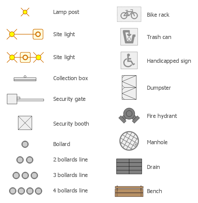
Fault Tree Diagram are logic diagram that shows the state of an entire system in a relationship of the conditions of its elements. Fault Tree Diagram are used to analyze the probability of functional system failures and safety accidents. ConceptDraw PRO allows you to create professional Fault Tree Diagrams using the basic FTD symbols. An FTD visualize a model of the processes within a system that can lead to the unlikely event. A fault tree diagrams are created using standard logic symbols . The basic elements in a fault tree diagram are gates and events.The design elements library Site accessories contains 18 symbols of vehicle access control equipment (tollbooth, tollgate, parking fees payment box), a handicapped sign, outdoor lighting, and garbage receptacles.
"A site plan is an architectural plan, landscape architecture document, and a detailed engineering drawing of proposed improvements to a given lot. A site plan usually shows a building footprint, travelways, parking, drainage facilities, sanitary sewer lines, water lines, trails, lighting, and landscaping and garden elements." [Site plan. Wikipedia]
Use the Site accessories library to design plans, equipment layouts and maps of sites, parking lots, residential and commercial landscapes, parks, yards, plats, outdoor recreational facilities, and irrigation systems using ConceptDraw PRO diagramming and vector drawing software.
The design elements library Site accessories is contained in the Site Plans solution from the Building Plans area of ConceptDraw Solution Park.
- Gate Floor Plan Symbol
- Whats The Symbol For Gate On A Site Plan
- Symbol For A Gate In Landscape Design
- How To use House Electrical Plan Software | Electrical Symbols ...
- Site Plan Drawing Symbols Gate
- Electrical Drawing Software and Electrical Symbols | How To use ...
- Interior Design Site Plan - Design Elements | Design elements - Site ...
- Symbols Of The Gate In The Landscape Design Plan
- How To use House Electrical Plan Software | Electrical Symbols ...
- Symbol Of Gate In Architectural Drawing
- Design elements - Site accessories | Manhole Symbol Show In ...
- Symbol Of A Gate Floor Plan
- Symbol Of Gate Door
- Gate Valve Symbol Drawings
- Architectural Diagram Showing Gate Plan
- Design elements - HVAC controls | Physical Security Plan | 2-bit ...
- Electrical Engineering | Electrical Symbol For Safety Gate
- Design elements - Site accessories | Interior Design Site Plan ...
- How To use House Electrical Plan Software | Fire Exit Plan . Building ...
- Design elements - Logic gate diagram | Electrical Symbols ...

