"The symbols and conventions used in welding documentation are specified in national and international standards such as ISO 2553 Welded, brazed and soldered joints -- Symbolic representation on drawings and ISO 4063 Welding and allied processes -- Nomenclature of processes and reference numbers. The US standard symbols are outlined by the American National Standards Institute and the American Welding Society and are noted as "ANSI/ AWS".
In engineering drawings, each weld is conventionally identified by an arrow which points to the joint to be welded. The arrow is annotated with letters, numbers and symbols which indicate the exact specification of the weld. In complex applications, such as those involving alloys other than mild steel, more information may be called for than can comfortably be indicated using the symbols alone. Annotations are used in these cases." [Symbols and conventions used in welding documentation. Wikipedia]
The example chart "Elements of welding symbol" is redesigned using the ConceptDraw PRO diagramming and vector drawing software from the Wikipedia file: Elements of a welding symbol.PNG.
[en.wikipedia.org/ wiki/ File:Elements_ of_ a_ welding_ symbol.PNG]
The diagram example "Elements location of a welding symbol" is contained in the Mechanical Engineering solution from the Engineering area of ConceptDraw Solution Park.
Welding joint symbol chart

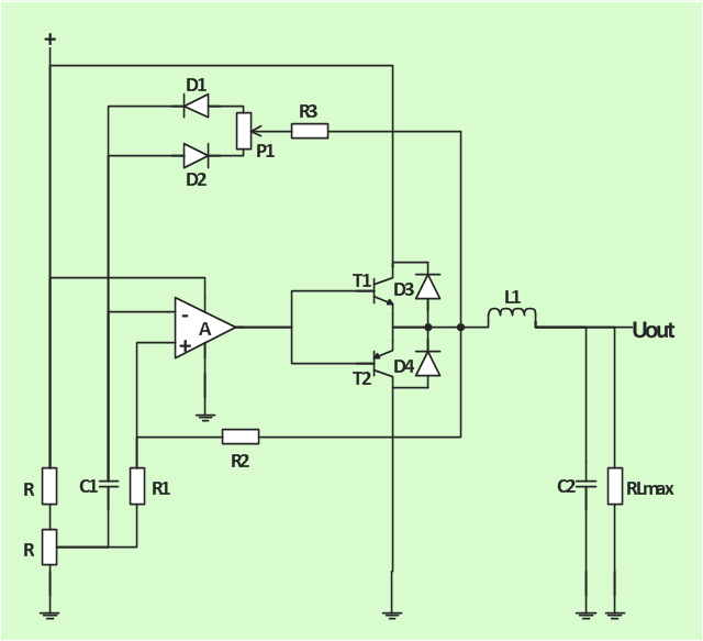
The analogue electronics diagram "Simple switched supply" was redesigned from the Wikimedia Commons file: Switchat.png.
[commons.wikimedia.org/ wiki/ File:Switchat.png]
"Analogue electronics (or analog in American English) are electronic systems with a continuously variable signal, in contrast to digital electronics where signals usually take only two different levels. The term "analogue" describes the proportional relationship between a signal and a voltage or current that represents the signal." [Analogue electronics. Wikipedia]
The circuit diagram example "Simple switched supply" was created using the ConceptDraw PRO diagramming and vector drawing software extended with the Electrical Engineering solution from the Engineering area of ConceptDraw Solution Park.
Circuit diagram
This vector stencils library contains 30 clipart images and astronomical symbols of sun and stars, solar system planets and moon.
Use these shapes for drawing your astronomical diagrams and illustrations.
Use these shapes for drawing your astronomical diagrams and illustrations.
Solar system
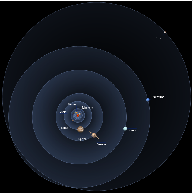
Sun

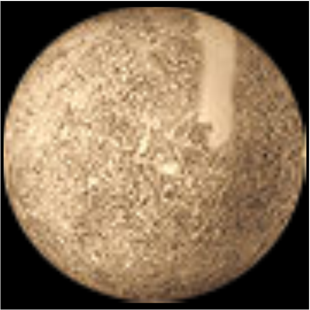
Mercury
Venus

Earth

Moon

Mars

Jupiter

Saturn

Uranus

Neptune

Pluto

Red giant

Yellow giant

Blue giant

Red dwarf

White dwarf

Black hole

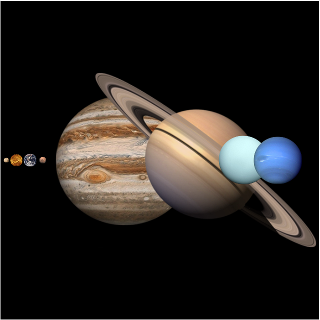
Planets to scale
Sun symbol

Mercury symbol

Venus symbol

Earth symbol
Moon symbol

Mars symbol
Jupiter symbol

Saturn symbol

Neptune symbol

Uranus symbol
Pluto symbol

 Event-driven Process Chain Diagrams
Event-Driven Process Chain Diagrams solution extends ConceptDraw DIAGRAM functionality with event driven process chain templates, samples of EPC engineering and modeling the business processes, and a vector shape library for drawing the EPC diagrams and EPC flowcharts of any complexity. It is one of EPC IT solutions that assist the marketing experts, business specialists, engineers, educators and researchers in resources planning and improving the business processes using the EPC flowchart or EPC diagram. Use the EPC solutions tools to construct the chain of events and functions, to illustrate the structure of a business process control flow, to describe people and tasks for execution the business processes, to identify the inefficient businesses processes and measures required to make them efficient.
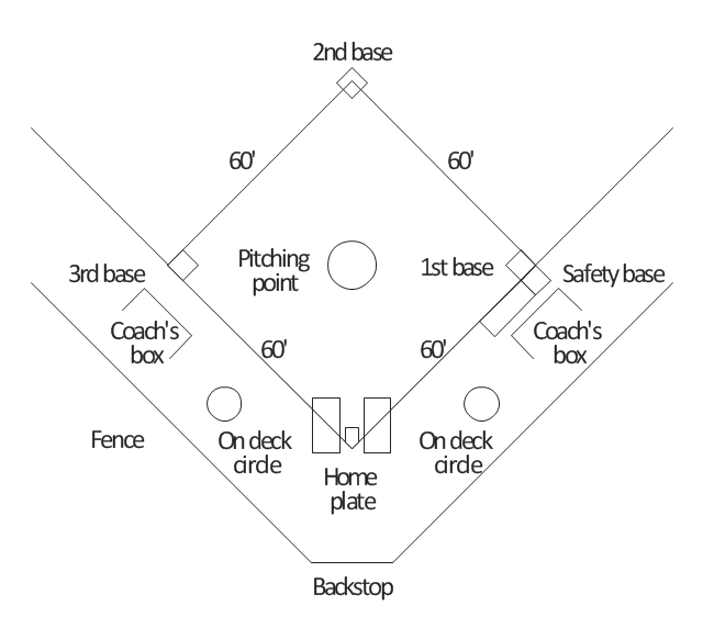
"A baseball field, also called a ball field or a baseball diamond, is the field upon which the game of baseball is played. The term is also used as a metonym for baseball park. ...
The starting point for much of the action on the field is home plate, which is a five-sided slab of whitened rubber, 17-inches square with two of the corners removed so that one edge is 17 inches long, two adjacent sides are 8½ inches and the remaining two sides are 12 inches and set at an angle to make a point. Adjacent to each of the two parallel 8½-inch sides is a batter's box. The point of home plate where the two 12-inch sides meet at right angles, is at one corner of a ninety-foot square. The other three corners of the square, in counterclockwise order from home plate, are called first base, second base, and third base. Three canvas bags fifteen inches (38 cm) square mark the three bases. These three bags along with home plate form the four bases at the corners of the infield." [Baseball field. Wikipedia]
The diagram example "Simple baseball field" was created using the ConceptDraw PRO diagramming and vector drawing software extended with the Baseball solution from the Sport area of ConceptDraw Solution Park.
Baseball field diagram
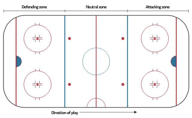
"An ice hockey arena (or ice hockey venue) is a sport venue in which an ice hockey competition is held. A lot of hockey arenas were designed for use by multiple types of sport." [Ice hockey arena. Wikipedia]
The diagram template "Simple hockey rink" for the ConceptDraw PRO diagramming and vector drawing software is included in the Hockey solution from the Sport area of ConceptDraw Solution Park.
The diagram template "Simple hockey rink" for the ConceptDraw PRO diagramming and vector drawing software is included in the Hockey solution from the Sport area of ConceptDraw Solution Park.
Ice hockey rink diagram template
Tree Network Topology Diagram

UML Diagram

Pyramid Chart Examples

UML Class Diagram Generalization Example UML Diagrams

- Elements location of a welding symbol | Welding symbols | Design ...
- Elements location of a welding symbol | Material Requisition ...
- Wan Network Simple Diagram Wikipedia
- Machine Symbol And Surface Texture Wikipedia
- Speaker Symbol In Engineering Drawing
- Elements location of a welding symbol | Welding symbols | Elements ...
- Welding symbols | Elements location of a welding symbol | Design ...
- Electrical Geyser Wikipedia
- Elements location of a welding symbol | Elements location of a ...