How to make great presentation via Skype? ...how it works with ConceptDraw MINDMAP?
The Brainstorming session is successfully conducted, professional-looking Mind Map is designed, but how to present it to colleagues? The mindmapping software with ability of showing the business presentation via Skype is valuable. The Remote Presentation for Skype solution enhances the ConceptDraw MINDMAP software with useful ability to deliver the presentations via Skype. With it you can make great presentations, develop your own presentation style and remotely present the business documents to all participants of Skype conference call. Simply click the Show Presentation via Skype button in ConceptDraw MINDMAP application, the presentation file will be synchronized and Skype presentation will be demonstrated as a slide show at all computers of Skype conference participants, you need only control the presentation slides. Using current voice call you can tell your presentation story and discuss it. At the end of presentation made via Skype, each participant has its own copy of presentation document file saved in Presentation History folder and will be able to see it again, if he wants.What is MindMap presentation via Skype?
Skype is incredibly popular program, used by millions of people in all over the world as a means of communication and sharing the information, data, documents and other files. The Skype opportunities for business are obvious and limitless, besides it is a global standard for video web conferencing. The Remote Presentation for Skype solution supplies the ConceptDraw MINDMAP with perfect ability to hold the Skype conferences with your team, effectively exchange the documents and present them live via Skype, allowing the coworkers from anywhere in the world to view their briefing while hearing their voice. The Mind Map Exchange solution contributes for easy importing and exporting documents between ConceptDraw MINDMAP and other most popular mindmapping software, such as MindJet Mindmanager, Freemind, XMind, also MS Word and other applications. At the end of Skype conference held at the assist of Remote Presentation for Skype solution, each participant receives the copy of presentation document file and can find it at Presentation History folder, viewed again or shown for other team.HelpDesk
How to Activate ConceptDraw After Purchasing from the Web Store
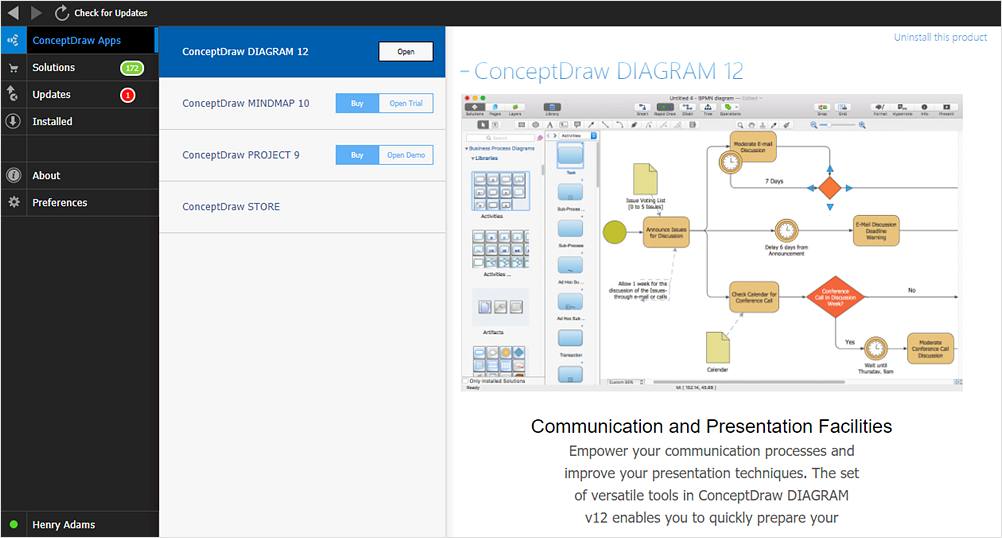
Here you will find an explanation of how activation works when ConceptDraw products are purchased from the ConceptDraw web site. You do not have to manually activate your software. Your license key is saved in your account. Your license is automatically added to your ConceptDraw.com account and saved there permanently. Thus you don’t have to worry about losing your license if your computer crashes or you want to install on a second system.UML Activity Diagram. Design Elements
UML Activity Diagram illustrate the business and operational step-by-step workflow of components in a system and shows the overall flow of control.
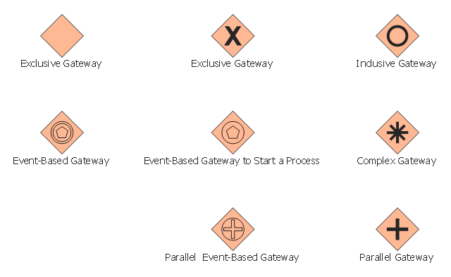
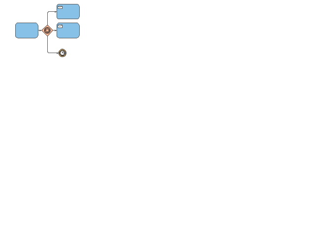
The vector stencils library "Gateways" contains 8 symbols of exclusive, event-based, parallel, inclusive and complex gateways.
Use these shapes for creating the business process diagrams using the ConceptDraw PRO diagramming and vector drawing software.
"Gateway.
A gateway is represented with a diamond shape and determines forking and merging of paths, depending on the conditions expressed.
Exclusive.
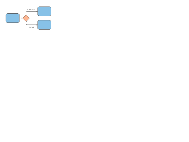
Used to create alternative flows in a process because only one of the paths can be taken, it is called exclusive.
Event Based.
The condition determining the path of a process is based on an evaluated event.
Parallel.
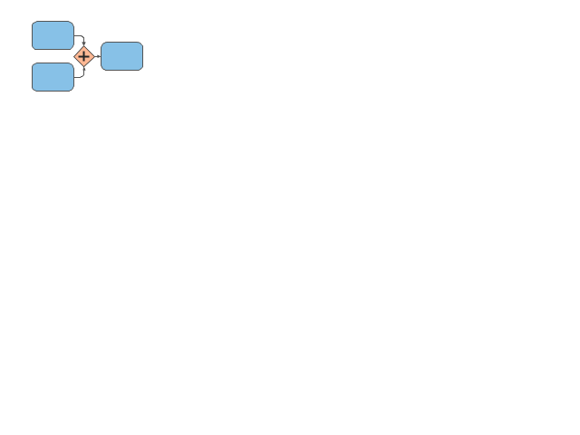
Used to create parallel paths without evaluating any conditions.
Inclusive.
Used to create alternative flows where all paths are evaluated.
Exclusive Event Based.
An event is being evaluated to determine which of mutually exclusive paths will be taken.
Complex.
Used to model complex synchronization behavior.
Parallel Event Based.
Two parallel process are started based on an event but there is no evaluation of the event." [Business Process Model and Notation. Wikipedia]
The example "Design elements - Gateways BPMN 2.0" is included in the Business Process Diagram solution from the Business Processes area of ConceptDraw Solution Park.
Product Overview
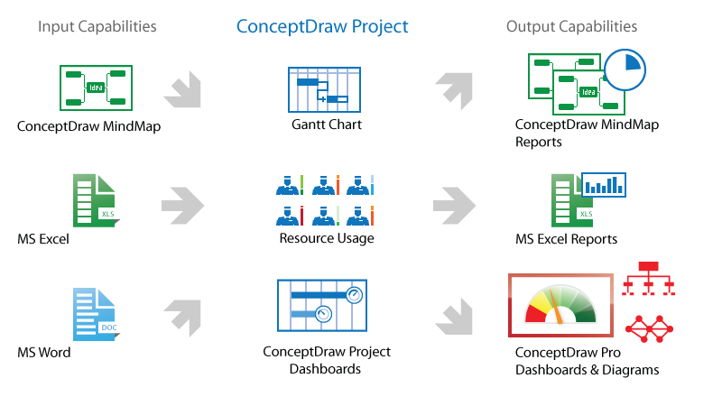
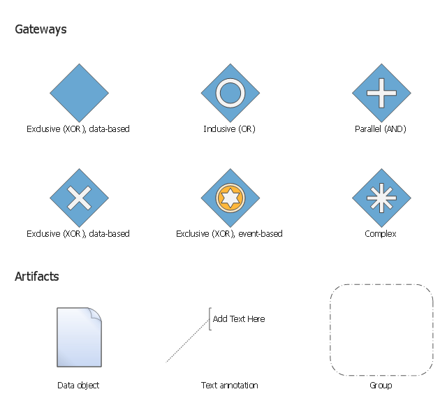
ConceptDraw PROJECT is a vigorous tool for managing single or multiple projects. It lets you determine all essential elements involved into project, control schedules, resources and finances, and monitor projects' progress in most effective yet simple manner.The vector stencils library "Gateways BPMN 1.2" contains symbols: data-based and event-based exclusive (XOR), inclusive (OR), parallel (AND), complex.
The vector stencils library "Artifacts BPMN 1.2" contains symbols: data object, text annotation, and group.
Use these shapes for creating the business process diagrams using the ConceptDraw PRO diagramming and vector drawing software.
"Gateway.
A gateway is represented with a diamond shape and determines forking and merging of paths, depending on the conditions expressed.
Exclusive.
Used to create alternative flows in a process because only one of the paths can be taken, it is called exclusive.
Event Based.
The condition determining the path of a process is based on an evaluated event.
Parallel.
Used to create parallel paths without evaluating any conditions.
Inclusive.
Used to create alternative flows where all paths are evaluated.
Exclusive Event Based.
An event is being evaluated to determine which of mutually exclusive paths will be taken.
Complex.
Used to model complex synchronization behavior.
Parallel Event Based.
Two parallel process are started based on an event but there is no evaluation of the event. ...
Artifacts allow developers to bring some more information into the model/ diagram. In this way the model/ diagram becomes more readable. There are three pre-defined Artifacts and they are:
(1) Data objects: Data objects show the reader which data is required or produced in an activity.
(2) Group: A Group is represented with a rounded-corner rectangle and dashed lines. The group is used to group different activities but does not affect the flow in the diagram.
(3) Annotation: An annotation is used to give the reader of the model/ diagram an understandable impression." [Business Process Model and Notation. Wikipedia]
The example "Design elements - Gateways and artifacts BPMN 1.2" is included in the Business Process Diagram solution from the Business Processes area of ConceptDraw Solution Park.
The vector stencils library "Expanded objects" contains 14 expanded object symbols.
Use these shapes for drawing business process diagrams (BPMN 2.0) in the ConceptDraw PRO diagramming and vector drawing software extended with the Business Process Diagram solution from the Business Processes area of ConceptDraw Solution Park.
www.conceptdraw.com/ solution-park/ business-process-diagram
UML Notation
Unified Modeling Language (UML) is an open standard, the language of graphic description used for modeling objects in a field of software development and software engineering. It was created for definition, specification, visualization, designing and documenting software systems, as a unification of three object-oriented technologies Booch, OMT and OOSE, and uses the defined graphic notation for creating the visual models of object-oriented software systems. Description of UML consists of two parts, interactive and supplementing each other: UML semantics, which represents a certain metamodel, defines the abstract syntax and semantics of terms of object modeling with UML, and UML notation that is a graphic notation for visual representation of UML semantics. The powerful tools of the Rapid UML solution included to ConceptDraw Solution Park make the ConceptDraw DIAGRAM diagramming and vector drawing software the best for easy applying the UML notation when creating the visual models of object-oriented software systems and designing different kinds of UML diagrams.- How to make great presentation via Skype? ...how it works with ...
- Mind Mapping Software
- What is MindMap presentation via Skype? | What Is an Action Mind ...
- How to Import Mind Maps from FreeMind | How to make great ...
- Audio, Video, Media | Mind Map Food | MindMap Presentation ...
- How to exchange data files of Mindjet Mindmanager ? | How to do ...
- How to Exchange ConceptDraw MINDMAP Files with Mindjet ...
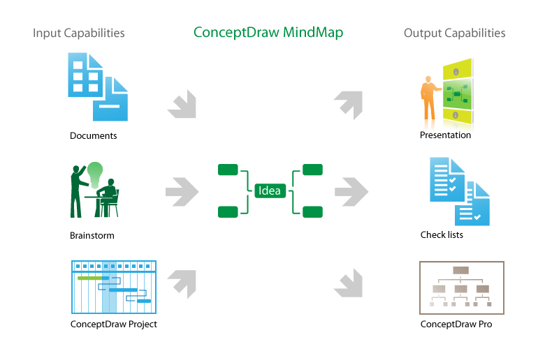
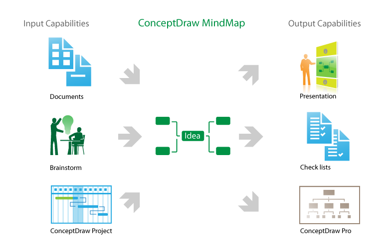
- One formula of professional mind mapping : input data + output data ...
- How to Import Mind Maps from XMind | How to make great ...
- How to do presentation of Mind Maps via Skype conference call ...
- Mind Map Making Software | How to make great presentation via ...
- How to view a mind map presentation via Skype | Creating a default ...
- Mind Map Making Software | Mind Map Food | How To Do A Mind ...
- Create Captivating Presentations Easily | One formula of ...
- Looking at ConceptDraw MINDMAP as a Replacement for Mindjet ...
- How to Import Mind Maps from XMind | How to Print an Outline ...
- How to Import Mind Maps from FreeMind | The Mind Map Evernote ...
- Project Exchange | Export from ConceptDraw MINDMAP to MS ...
- Evernote & Exchange Integrations | Create Captivating ...
- Export from ConceptDraw MINDMAP into MS Word Document | How ...
