"Network planning and design is an iterative process, encompassing topological design, network-synthesis, and network-realization, and is aimed at ensuring that a new telecommunications network or service meets the needs of the subscriber and operator. Network planning process involves three main steps: 1) Topological design: This stage involves determining where to place the components and how to connect them. 2) Network-synthesis: This stage involves determining the size of the components used, subject to performance criteria such as the Grade of Service (GoS). 3) Network realization: This stage involves determining how to meet capacity requirements, and ensure reliability within the network." [Network planning and design. Wikipedia]
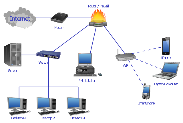
This computer network system design diagram example was created using the ConceptDraw PRO diagramming and vector drawing software extended with the Computer and Networks solution from the Computer and Networks area of ConceptDraw Solution Park.
This computer network system design diagram example was created using the ConceptDraw PRO diagramming and vector drawing software extended with the Computer and Networks solution from the Computer and Networks area of ConceptDraw Solution Park.
The design elements library "Cable TV" contains 64 symbols of CATV network equipment.
"Cable television is a system of distributing television programs to subscribers via radio frequency (RF) signals transmitted through coaxial cables or light pulses through fiber-optic cables. This contrasts with traditional broadcast television (terrestrial television) in which the television signal is transmitted over the air by radio waves and received by a television antenna attached to the television. FM radio programming, high-speed Internet, telephone service, and similar non-television services may also be provided through these cables.
The abbreviation CATV is often used for cable television." [Cable television. Wikipedia]
Use the shapes library "Cable TV" to draw CATV system design floor plans, network topology diagrams, wiring diagrams and cabling layout schemes using the ConceptDraw PRO diagramming and vector drawing software.
The vector stencils library "Cable TV" is included in the Electric and Telecom Plans solution from the Building Plans area of ConceptDraw Solution Park.
- Computer network system design diagram | How to Draw a ...
- Flowchart System Analysis Design
- Structured Systems Analysis and Design Method (SSADM) with ...
- Computer network system design diagram | Structured Systems ...
- Security and Access Plans | How to Draw a Security and Access ...
- System Design | SDL — Systems Engineering | FSM — Finite-state ...
- Computer network system design diagram | Design elements ...
- Computer network system design diagram | Cisco Design | Point-to ...
- Computer network system design diagram
- Network Diagram System Analysis Design
- Computer network system design diagram | Draw Synthesis Process ...
- Computer network system design diagram
- Basic CCTV System Diagram. CCTV Network Diagram Example ...
- Computer network system design diagram | Wireless Network ...
- Computer network system design diagram | Computer Network ...
- System Design And Flowchart
- Computer network system design diagram | Draw The Diagram Of ...
- How To Design Network System
- System Design With Flow Chart Data Flow Diagram
- Mechanical System Design Symbol

.png--diagram-flowchart-example.png)