This vehicular network diagram example was drawn on the base of the picture "Inter-Vehicle Communication (IVC) systems" from the website of the Department of Electrical and Computer Engineering, the Ohio State University.
[www2.ece.ohio-state.edu/ ~ekici/ res_ ivc.html]
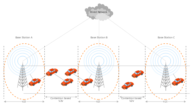
"Driver assistance systems are meant to support drivers with driving process in order to avoid traffic accidents, speed up the traffic and have a higher control over the traffic in general. There are a lot of systems which give support to the drivers, such as adaptive cruise control, traffic sign recognition, automatic parking, etc. ... the vehicular communication systems ... use the capacity of the vehicles to communicate, not only between them but also with infrastructures. All the information is collected and processed to offer use
ful services. Wireless Sensor Networks (WSN) are widely used in this area. With the incoming upgrades of these networks, they are becoming an attractive solution to give support with the communication mechanisms between vehicles." [mi.fu-berlin.de/ inf/ groups/ ag-tech/ teaching/ 2011_ SS/ S_ 19510b_ Proseminar_ Technische_ Informatik/ daniel-lopez-report.pdf?1346662267]
The vehicular network diagram example "Inter-vehicle communication systems" was created using the ConceptDraw PRO diagramming and vector drawing software extended with the Vehicular Networking solution from the Computer and Networks area of ConceptDraw Solution Park.
[www2.ece.ohio-state.edu/ ~ekici/ res_ ivc.html]
"Driver assistance systems are meant to support drivers with driving process in order to avoid traffic accidents, speed up the traffic and have a higher control over the traffic in general. There are a lot of systems which give support to the drivers, such as adaptive cruise control, traffic sign recognition, automatic parking, etc. ... the vehicular communication systems ... use the capacity of the vehicles to communicate, not only between them but also with infrastructures. All the information is collected and processed to offer use
ful services. Wireless Sensor Networks (WSN) are widely used in this area. With the incoming upgrades of these networks, they are becoming an attractive solution to give support with the communication mechanisms between vehicles." [mi.fu-berlin.de/ inf/ groups/ ag-tech/ teaching/ 2011_ SS/ S_ 19510b_ Proseminar_ Technische_ Informatik/ daniel-lopez-report.pdf?1346662267]
The vehicular network diagram example "Inter-vehicle communication systems" was created using the ConceptDraw PRO diagramming and vector drawing software extended with the Vehicular Networking solution from the Computer and Networks area of ConceptDraw Solution Park.
Vehicular network diagram
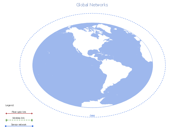
A conceptual diagram of a global vehicular network describes the principles of communication between vehicles, earth-based nodes, and space-based nodes in a wireless network. It illustrates the concept of architecture within global vehicular networks.
"Intelligent transportation systems (ITS) are advanced applications which, without embodying intelligence as such, aim to provide innovative services relating to different modes of transport and traffic management and enable various users to be better informed and make safer, more coordinated, and 'smarter' use of transport networks.
...
Intelligent transport systems vary in technologies applied, from basic management systems such as car navigation; traffic signal control systems; container management systems; variable message signs; automatic number plate recognition or speed cameras to monitor applications, such as security CCTV systems; and to more advanced applications that integrate live data and feedback from a number of other sources, such as parking guidance and information systems; weather information; bridge deicing systems; and the like." [Intelligent transportation system. Wikipedia]
The global vehicular network diagram template is included in the Vehicular Networking solution from the Computer and Networks area of ConceptDraw Solution Park.
Global vehicular network diagram template
UML Activity Diagram

UML Diagram of Parking

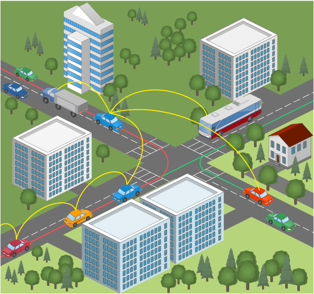
This vehicular network diagram sample was drawn on the base of picture illustrating the post "Intelligent transportation system" from the blog "Technology New Here".
"Intelligent transportation systems are projects that aim to integrate modern communication and information technology into existing transportation management systems in order to optimize vehicle life, fuel efficiency, safety, and traffic in urbanized cities.
The need for intelligent transportation systems stems from the fact that traffic congestion has been increasing all around the world because of increasing population, increasing amount of transportation vehicles and increasing urbanization."
[technologynewhere.wordpress.com/ 2010/ 05/ 12/ intelligent-transportation-system/ ]
The vehicular network diagram example "Intelligent transportation system" was created using the ConceptDraw PRO diagramming and vector drawing software extended with the Vehicular Networking solution from the Computer and Networks area of ConceptDraw Solution Park.
Vehicular network diagram
The vector stencils library Alarm and access control contains 80 symbols of digital proximity equipment, locking hardware, and access control equipment.
"An alarm device or system of alarm devices gives an audible, visual or other form of alarm signal about a problem or condition. Alarm devices are often outfitted with a siren." [Alarm device. Wikipedia]
"An access control point, which can be a door, turnstile, parking gate, elevator, or other physical barrier, where granting access can be electronically controlled. Typically, the access point is a door. An electronic access control door can contain several elements. At its most basic, there is a stand-alone electric lock. The lock is unlocked by an operator with a switch. To automate this, operator intervention is replaced by a reader. The reader could be a keypad where a code is entered, it could be a card reader, or it could be a biometric reader. Readers do not usually make an access decision, but send a card number to an access control panel that verifies the number against an access list. To monitor the door position a magnetic door switch can be used. In concept, the door switch is not unlike those on refrigerators or car doors. Generally only entry is controlled, and exit is uncontrolled. In cases where exit is also controlled, a second reader is used on the opposite side of the door. In cases where exit is not controlled, free exit, a device called a request-to-exit (REX) is used. Request-to-exit devices can be a push-button or a motion detector. When the button is pushed, or the motion detector detects motion at the door, the door alarm is temporarily ignored while the door is opened. Exiting a door without having to electrically unlock the door is called mechanical free egress. This is an important safety feature. In cases where the lock must be electrically unlocked on exit, the request-to-exit device also unlocks the door." [Access control. Wikipedia]
Use the design elements library Alarm and access control for drawing layout floor plans, blueprints, and wiring diagrams of intrusion systems, time and attendance systems, card and code access control security systems, internal and external security control systems using the ConceptDraw PRO diagramming and vector drawing software.
The shapes library Alarm and access control is included in the Security and Access Plans solution from the Building Plans area of ConceptDraw Solution Park.
Alarm and access control symbols

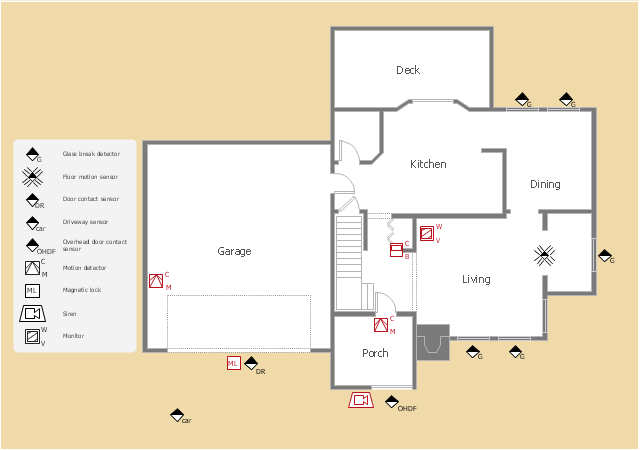
"A security alarm is a system designed to detect intrusion – unauthorized entry – into a building or area. Security alarms are used in residential, commercial, industrial, and military properties for protection against burglary (theft) or property damage, as well as personal protection against intruders. Car alarms likewise protect vehicles and their contents. Prisons also use security systems for control of inmates.
Some alarm systems serve a single purpose of burglary protection; combination systems provide both fire and intrusion protection. Intrusion alarm systems may also be combined with closed-circuit television surveillance systems to automatically record the activities of intruders, and may interface to access control systems for electrically locked doors. Systems range from small, self-contained noisemakers, to complicated, multi-area systems with computer monitoring and control." [Security alarm. Wikipedia]
The example "Security system plan" was created using the ConceptDraw PRO diagramming and vector drawing software extended with the Security and Access Plans solution from the Building Plans area of ConceptDraw Solution Park.
Security system plan
- HVAC Plans | How to Create a HVAC Plan | Block diagram ...
- Inter- vehicle communication systems | Land sales process flowchart ...
- Accident Diagram Car Template
- Block diagram - Automotive HVAC system | HVAC Plans | HVAC ...
- Block diagram - Automotive HVAC system | Functional Block ...
- Block diagram - Automotive HVAC system | Create Block Diagram ...
- Car Sensor Symbols And Meanings
- Block diagram - Automotive HVAC system | Functional Block ...
- UML activity diagram - Alarm trigger processing | Security system ...
- UML Activity Diagram | UML Diagram of Parking | Process Flowchart ...
- Independent regional networks diagram | Inter- vehicle ...
- State Diagram For Car Parking System
- Automated Car Parking System Use Case Diagram
- Car Air Flow Sensor Blueprint Plan
- UML Tool & UML Diagram Examples | UML Activity Diagram | UML ...
- Intelligent transportation system | Global vehicular network diagram ...
- How to Create a Vehicular Network Diagram | Vehicular Networking ...
- Diagram Of Car
- Inter- vehicle communication systems | Vehicular Networking ...
- Vehicular Networking | Inter- vehicle communication systems ...