 Plumbing and Piping Plans
Plumbing and Piping Plans solution extends ConceptDraw DIAGRAM.2.2 software with samples, templates and libraries of pipes, plumbing, and valves design elements for developing of water and plumbing systems, and for drawing Plumbing plan, Piping plan, PVC Pipe plan, PVC Pipe furniture plan, Plumbing layout plan, Plumbing floor plan, Half pipe plans, Pipe bender plans.
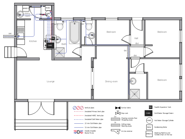
This plumbing and piping plan example depicts the house drinking water supply system.
"Drinking water, also known as potable water or improved drinking water, is water safe enough for drinking and food preparation." [Drinking water. Wikipedia]
"Modern indoor plumbing delivers clean, safe, potable water to each service point in the distribution system." [Tap water. Wikipedia]
The potable water system example "House tap water supply" was created using the ConceptDraw PRO diagramming and vector drawing software extended with the Plumbing and Piping Plans solution from the Building Plans area of ConceptDraw Solution Park.
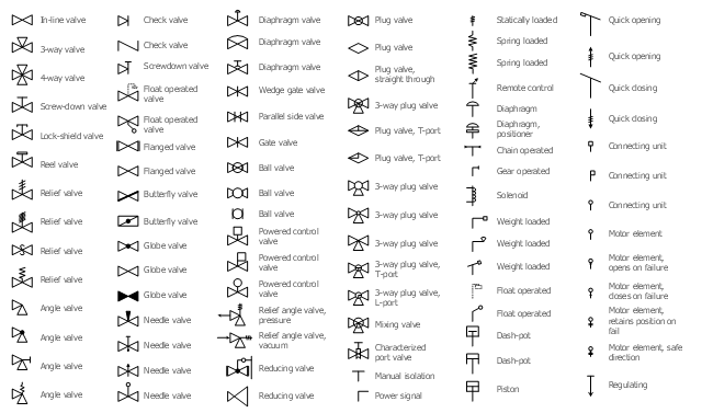
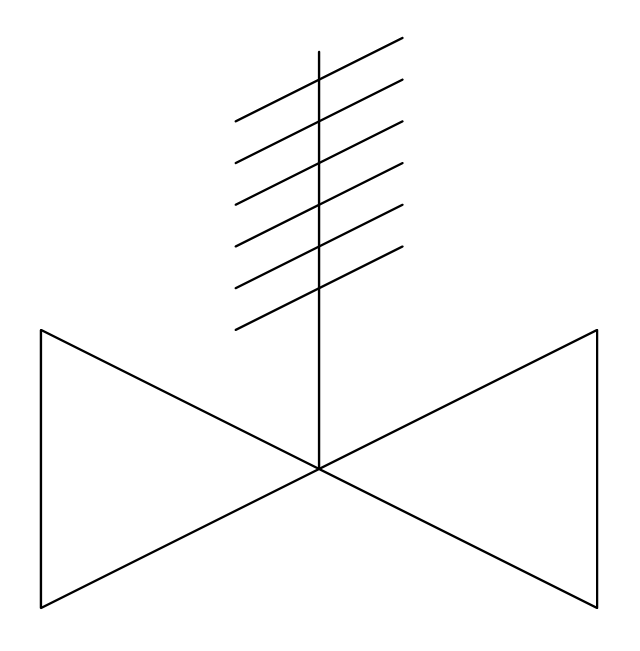
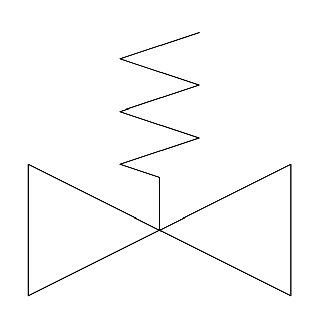
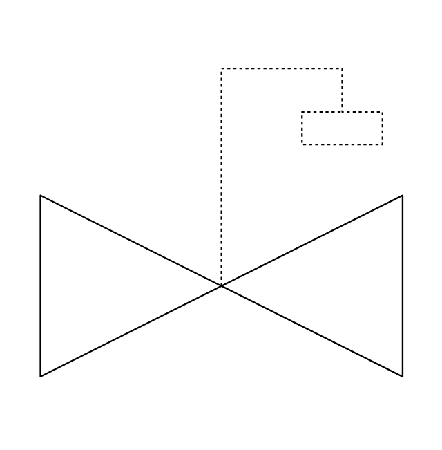
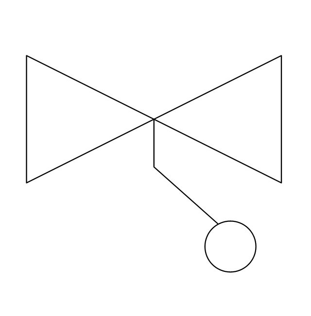
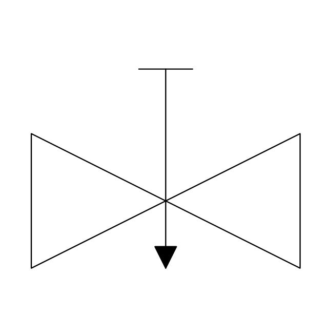
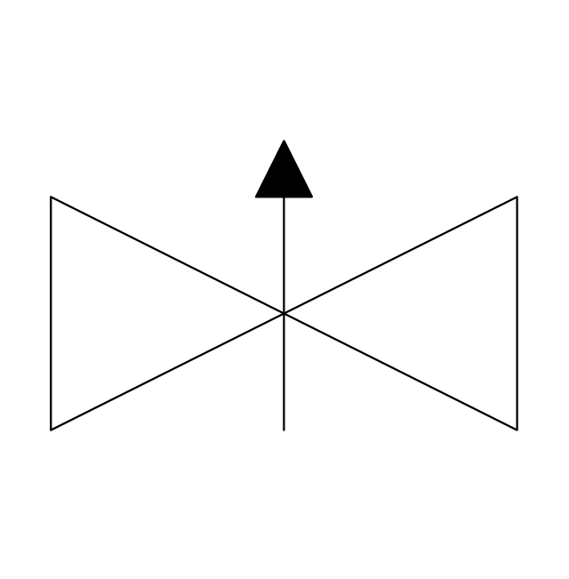
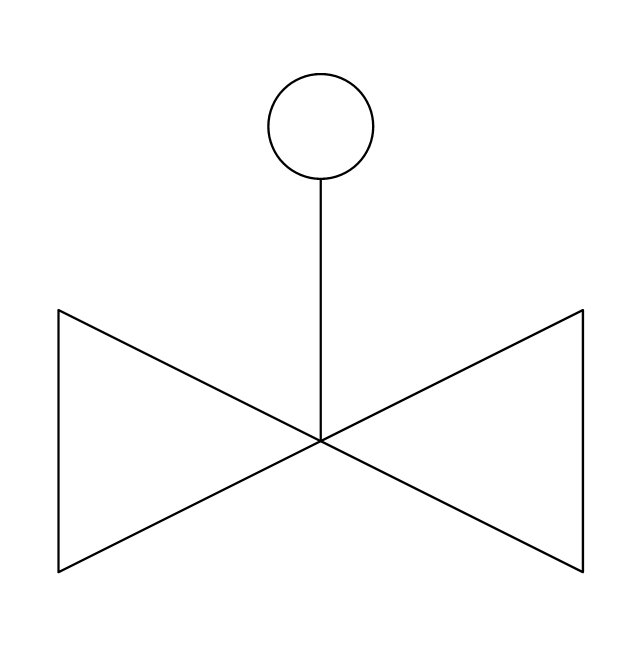
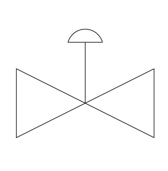
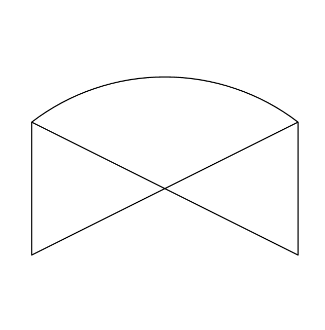
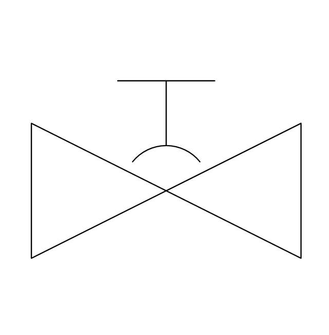
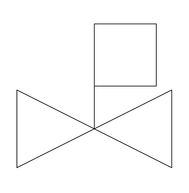
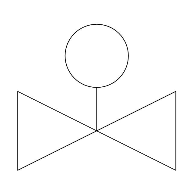
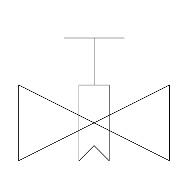
The vector stencils library "Valves" contains 91 symbols of piping and plumbing valves.
"A valve is a device that regulates, directs or controls the flow of a fluid (gases, liquids, fluidized solids, or slurries) by opening, closing, or partially obstructing various passageways. Valves are technically valves fittings, but are usually discussed as a separate category. In an open valve, fluid flows in a direction from higher pressure to lower pressure.
The simplest, and very ancient, valve is simply a freely hinged flap which drops to obstruct fluid (gas or liquid) flow in one direction, but is pushed open by flow in the opposite direction. This is called a check valve, as it prevents or "checks" the flow in one direction.
People in developed nations use valves in their daily lives, including plumbing valves, such as taps for tap water, gas control valves on cookers, small valves fitted to washing machines and dishwashers, safety devices fitted to hot water systems..." [Valve. Wikipedia]
Use the design elements library "Valves" to draw building plans, schematic diagrams, blueprints, or technical drawings of industrial piping systems; process, vacuum, and fluids piping; hydraulics piping; air and gas piping; materials distribution; and liquid transfer systems using the ConceptDraw PRO diagramming and vector drawing software.
The shapes library "Valves" is included in the Plumbing and Piping Plans solution from the Building Plans area of ConceptDraw Solution Park.
This plumbing and piping plan sample depicts the potable and hot tap water supply in the cafe.
"Tap water (running water, city water, municipal water, etc.) is water supplied to a tap (valve). Its uses include drinking, washing, cooking, and the flushing of toilets. Indoor tap water is distributed through "indoor plumbing"." [Tap water. Wikipedia]
The plumbing and piping plan example "Cafe water supply" was created using the ConceptDraw PRO diagramming and vector drawing software extended with the Plumbing and Piping Plans solution from the Building Plans area of ConceptDraw Solution Park.
 Plant Layout Plans
Plant Layout Plans solution can be used for power plant design and plant layout design, for making the needed building plant plans and plant layouts looking professionally good. Having the newest plant layout software, the plant design solutions and in particular the ConceptDraw’s Plant Layout Plans solution, including the pre-made templates, examples of the plant layout plans, and the stencil libraries with the design elements, the architects, electricians, interior designers, builders, telecommunications managers, plant design engineers, and other technicians can use them to create the professionally looking drawings within only a few minutes.
Process Flow Diagram Symbols
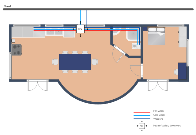
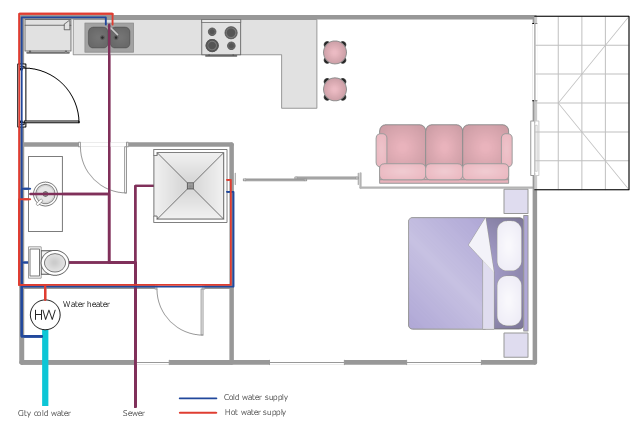
Chemical and Process Engineering Solution from the Industrial Engineering Area of ConceptDraw Solution Park is a unique tool which contains variety of predesigned process flow diagram symbols for easy creating various Chemical and Process Flow Diagrams in ConceptDraw DIAGRAM.This plumbing and piping plan sample shows the apartment hot and cold water supply and waste removal system.
It was drawn on the base of plumbing plan from the website of the Pennsylvania State University. [personal.psu.edu/ students/ k/ z/ kzz5000/ Final Presentation group work/ Drawing Sheets/ P101 - Plumbing Plan.jpg]
"" []
The tap water supply scheme example "Apartment plumbing plan" was created using the ConceptDraw PRO diagramming and vector drawing software extended with the Plumbing and Piping Plans solution from the Building Plans area of ConceptDraw Solution Park.
 Chemical and Process Engineering
This chemical engineering solution extends ConceptDraw DIAGRAM.9.5 (or later) with process flow diagram symbols, samples, process diagrams templates and libraries of design elements for creating process and instrumentation diagrams, block flow diagrams (BFD
The vector stencils library "Valves" contains 91 symbols of valves. Use it for drawing plumbing and piping plans, schematic diagrams and blueprints of industrial piping systems; process, vacuum, and fluids piping; hydraulics piping; air and gas piping; materials distribution; and liquid transfer systems in the ConceptDraw PRO diagramming and vector drawing software extended with the Plumbing and Piping Plans solution from the Building Plans area of ConceptDraw Solution Park.
This plumbing and piping plan example shows the flat potable and hot water supply system.
"Potable water supply ... may come from several possible sources.
* Municipal water supply
* Water wells
* Processed water from creeks, streams, rivers, lakes, rainwater, etc. ...
Domestic hot water is provided by means of water heater appliances, or through district heating. The hot water from these units is then piped to the various fixtures and appliances that require hot water, such as lavatories, sinks, bathtubs, showers, washing machines, and dishwashers." [Tap water. Wikipedia]
The water supply scheme sample "Flat plumbing plan" was created using the ConceptDraw PRO diagramming and vector drawing software extended with the Plumbing and Piping Plans solution from the Building Plans area of ConceptDraw Solution Park.
Electrical Symbols, Electrical Diagram Symbols
When drawing Electrical Schematics, Electrical Circuit Diagrams, Power Systems Diagrams, Circuit and Wiring Diagrams, Digital and Analog Logic Schemes, you will obligatory need the electrical symbols and pictograms to represent various electrical and electronic devices, such as resistors, wires, transistors, inductors, batteries, switches, lamps, readouts, amplifiers, repeaters, relays, transmission paths, semiconductors, generators, and many more. Today these symbols are internationally standardized, so the diagrams designed using them are recognizable and comprehensible by specialists from different countries. Electrical Engineering Solution included to ConceptDraw Solution Park provides 26 libraries with 926 commonly used electrical schematic and electrical engineering symbols making the reality the easy drawing of Electrical diagrams, schematics and blueprints. Now you need only a few minutes to create great-looking Electrical diagram, simply choose required electrical design elements from the libraries, drag them on the needed places at the document and connect in a suitable way.Create Floor Plans Easily with ConceptDraw DIAGRAM
How to create Floor Plan Design easy and effectively? You can invite an interior designer and trust this work to him, which is usually expensive and result may not always meet your expectations. Another way is to design it yourself, but at this case you need to have special skills, knowledges and abilities, among them basic knowledge of the composition rules, color theory, materials science and software for interior design development. The ability to use specialized software for drawing is especially valuable, useful and saves your time. ConceptDraw DIAGRAM is one of the best among similar software, it offers extensive functionality, powerful tools, a lot of features, and is simple for using, so can be applied by everyone without efforts. Enhanced with Floor Plans and other solutions from the Building Plans area, the ConceptDraw DIAGRAM software helps easily create unique and harmonious interior designs, and draw in desired scale professional-looking Floor Plans and Layouts for homes, apartments, hotels, offices, and other buildings. ConceptDraw DIAGRAM is a full Visio compatibility and better alternative for students, teachers and business professionals to reliably create kinds of flowcharts, organizational charts, network diagrams, floor plans, electrical diagrams, software design diagrams, maps and more.
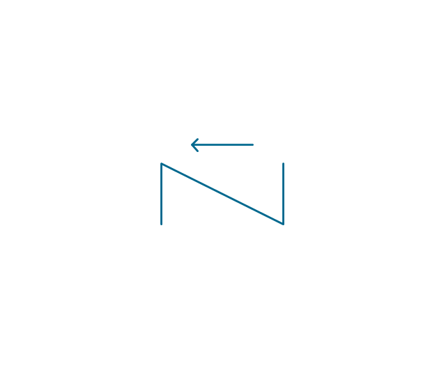
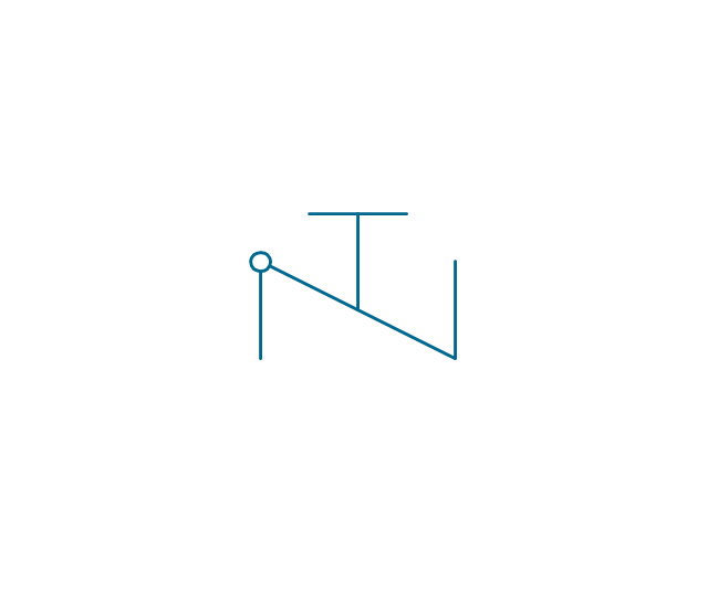
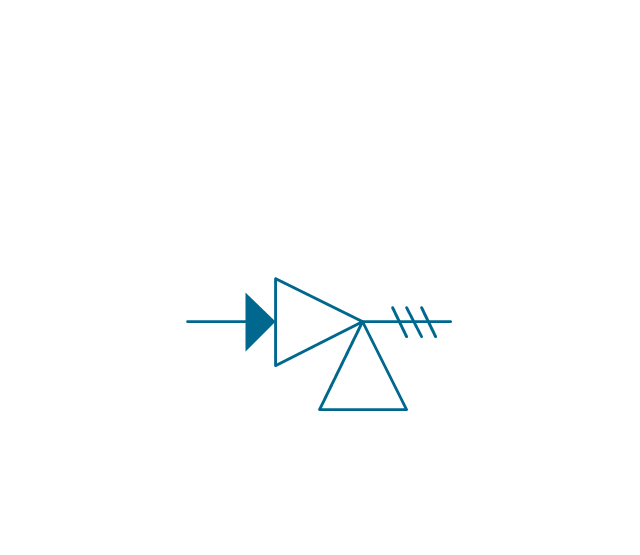
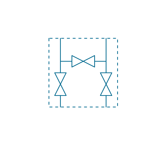
The vector stencils library "Valves and fittings" contains 104 symbols of valve components.
Use these icons for drawing industrial piping systems; process, vacuum, and fluids piping; hydraulics piping; air and gas piping; materials distribution; and liquid transfer systems in the ConceptDraw PRO software extended with the Chemical and Process Engineering solution from the Chemical and Process Engineering area of ConceptDraw Solution Park.
www.conceptdraw.com/ solution-park/ engineering-chemical-process
Chemical Engineering
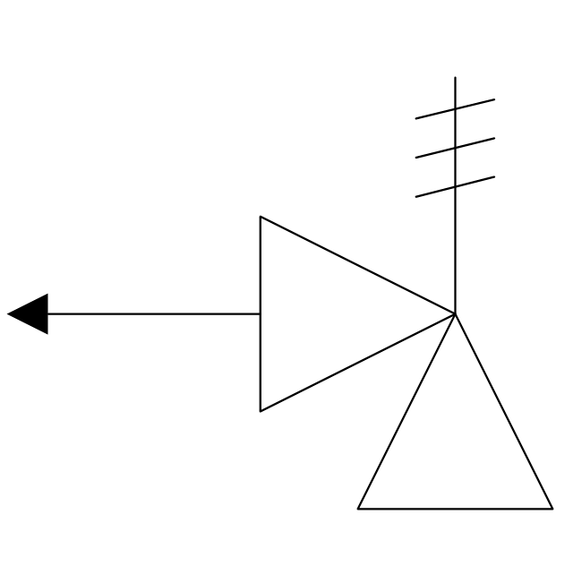
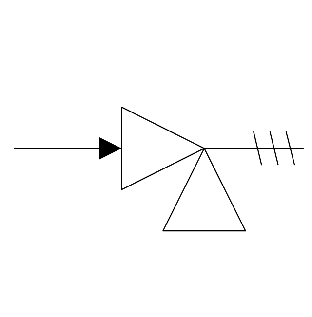
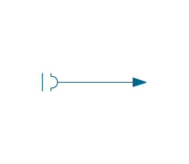
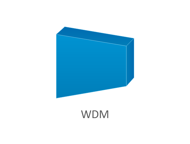
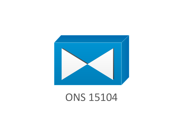
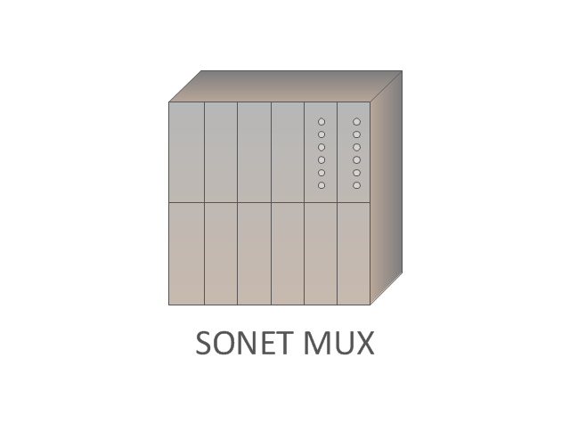
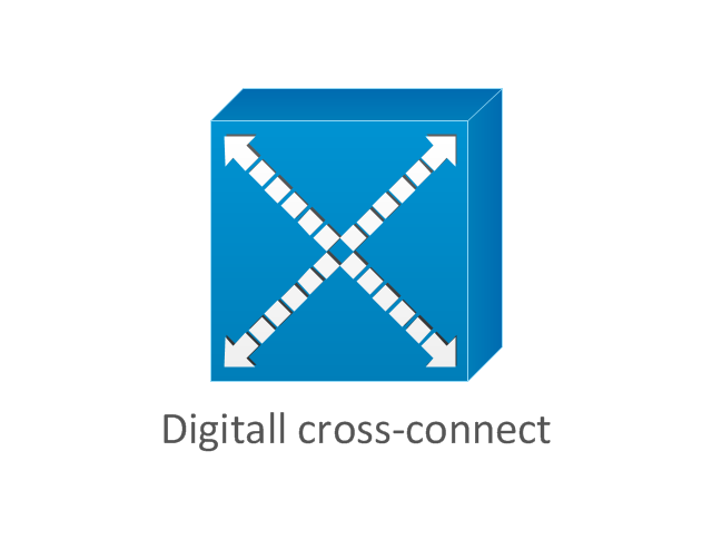
ConceptDraw DIAGRAM is a powerful diagramming and vector drawing software. Extended with Chemical and Process Engineering Solution from the Industrial Engineering Area of ConceptDraw Solution Park, it became the best Chemical Engineering software.The vector stencils library "Cisco optical" contains 19 symbols of optical devices for drawing Cisco computer network diagrams.
"Fiber-optic communication is a method of transmitting information from one place to another by sending pulses of light through an optical fiber. The light forms an electromagnetic carrier wave that is modulated to carry information. ... Because of its advantages over electrical transmission, optical fibers have largely replaced copper wire communications in core networks in the developed world. Optical fiber is used by many telecommunications companies to transmit telephone signals, Internet communication, and cable television signals. ...
The process of communicating using fiber-optics involves the following basic steps: Creating the optical signal involving the use of a transmitter, relaying the signal along the fiber, ensuring that the signal does not become too distorted or weak, receiving the optical signal, and converting it into an electrical signal." [Fiber-optic communication. Wikipedia]
The symbols example "Cisco optical - Vector stencils library" was created using the ConceptDraw PRO diagramming and vector drawing software extended with the Cisco Network Diagrams solution from the Computer and Networks area of ConceptDraw Solution Park.
www.conceptdraw.com/ solution-park/ computer-networks-cisco
- House tap water supply | Building Drawing Design Element: Piping ...
- Plumbing and Piping Plans | Tap Drawing Symbols Hot Cold
- Plumbing and Piping Plans | Tap Valve 1 Line Diagram
- Plumbing and Piping Plans | House plumbing drawing | House tap ...
- Plumbing and Piping Plans | Design elements - Valves | Process ...
- Plumbing and Piping Plans | Design elements - Valves | Ecology ...
- Plumbing and Piping Plans | Process Flowchart | Electrical Symbols ...
- Ductwork layout | Plumbing and Piping Plans | House tap water ...
- Mechanical Drawing Symbols | Process Flow Diagram Symbols ...
- Plumbing and Piping Plans | Building Drawing Design Element ...
- Cafe water supply | Health Food | A Running Water Tap Drawing
- Ductwork layout | House tap water supply | Plumbing and Piping ...
- Plumbing and Piping Plans | Process Flow Diagram Symbols | Water ...
- Plumbing and Piping Plans | Process Flow Diagram Symbols ...
- House tap water supply | Cafe water supply | Plumbing and Piping ...
- Symbole Household Water Taps In Pipe Fitting Diagram
- House tap water supply | Design elements - Plumbing | Drinking ...
- Tap Symbol Used In Building Planning Drawing
- Plant Layout Plans | Plumbing and Piping Plans | Dance studio floor ...
- Ablution Facilities Floor Plans With Water Taps Toilets Symbols































































































































































-cisco-optical---vector-stencils-library.png--diagram-flowchart-example.png)





-cisco-optical---vector-stencils-library.png--diagram-flowchart-example.png)
