Mechanical Drawing Symbols

 Mechanical Engineering
This solution extends ConceptDraw DIAGRAM.9 mechanical drawing software (or later) with samples of mechanical drawing symbols, templates and libraries of design elements, for help when drafting mechanical engineering drawings, or parts, assembly, pneumatic,
Mechanical Drawing Software

The vector stencils library "Hydraulic pumps and motors" contains 74 symbols of hydraulic pump vector stencils, hydraulic motor symbols for engineering drawings of fluid power and hydraulic control systems.
"Hydraulic pumps are used in hydraulic drive systems and can be hydrostatic or hydrodynamic.
Hydrostatic pumps are positive displacement pumps while hydrodynamic pumps can be fixed displacement pumps, in which the displacement (flow through the pump per rotation of the pump) cannot be adjusted, or variable displacement pumps, which have a more complicated construction that allows the displacement to be adjusted." [Hydraulic pump. Wikipedia]
"A hydraulic motor is a mechanical actuator that converts hydraulic pressure and flow into torque and angular displacement (rotation). The hydraulic motor is the rotary counterpart of the hydraulic cylinder.
Conceptually, a hydraulic motor should be interchangeable with a hydraulic pump because it performs the opposite function - much as the conceptual DC electric motor is interchangeable with a DC electrical generator. However, most hydraulic pumps cannot be used as hydraulic motors because they cannot be backdriven. Also, a hydraulic motor is usually designed for the working pressure at both sides of the motor.
Hydraulic pumps, motors, and cylinders can be combined into hydraulic drive systems. One or more hydraulic pumps, coupled to one or more hydraulic motors, constitutes a hydraulic transmission." [Hydraulic motor. Wikipedia]
The shapes example "Design elements - Hydraulic pumps and motors" was created using the ConceptDraw PRO diagramming and vector drawing software extended with the Mechanical Engineering solution from the Engineering area of ConceptDraw Solution Park.
Hydraulic pump and motor symbols

Mechanical Design Software

The vector stencils library "Hydraulic pumps and motors" contains 74 symbols of hydraulic equipment.
Use these shapes for engineering drawings of fluid power and hydraulic control systems in the ConceptDraw PRO diagramming and vector drawing software extended with the Mechanical Engineering solution from the Engineering area of ConceptDraw Solution Park.
www.conceptdraw.com/ solution-park/ engineering-mechanical
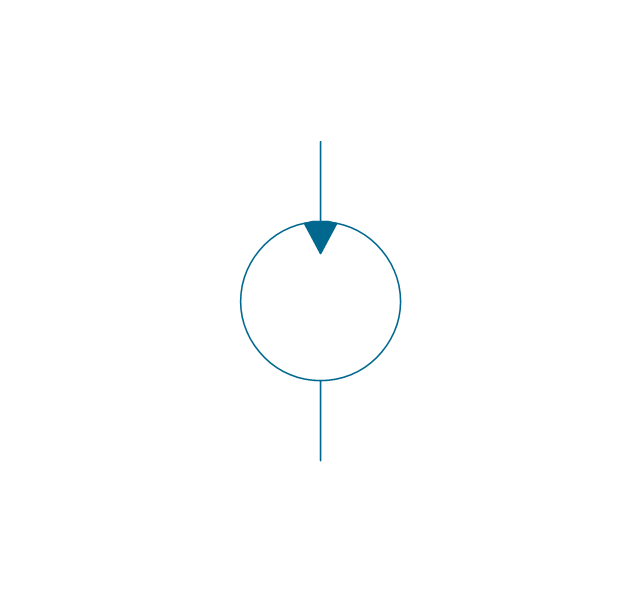
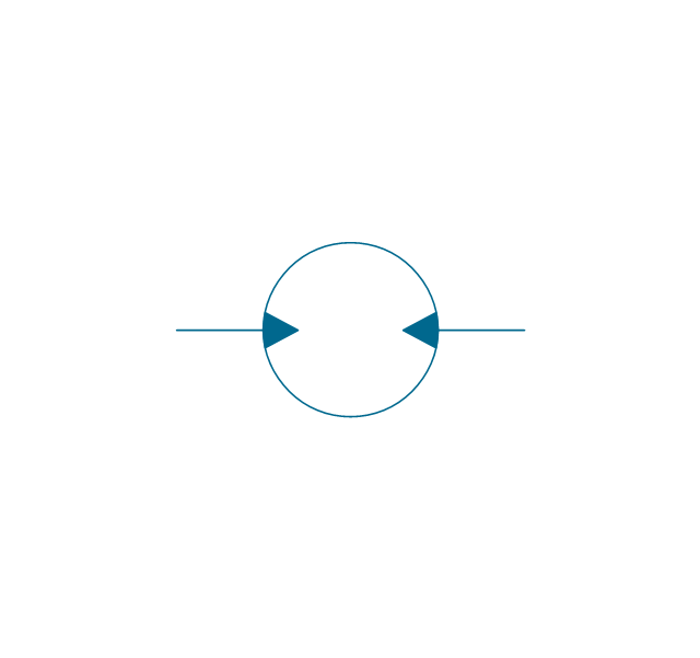
Pump, hydraulic

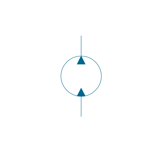
Motor, hydraulic
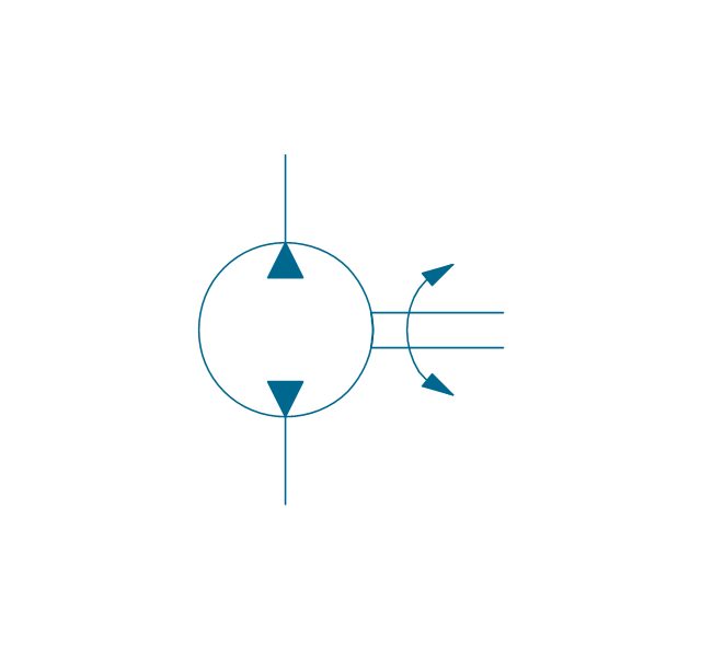
Pump-motor, hydraulic
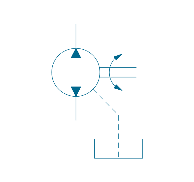
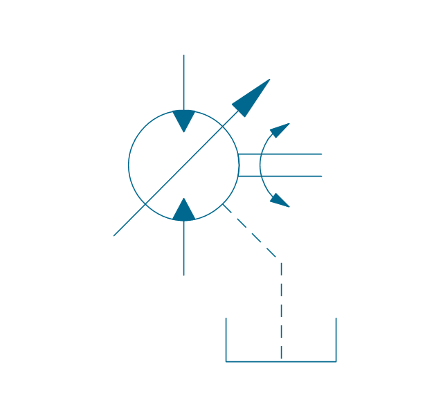
Pump, fixed, external drain
Pump, fixed, external drain
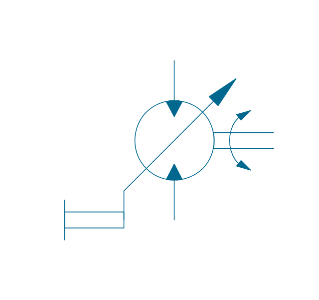
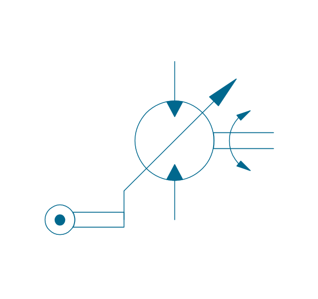
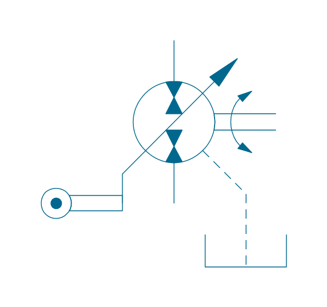
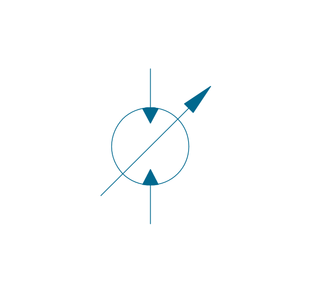
Pump, variable
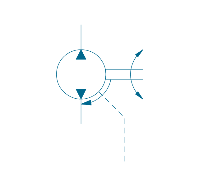
Pump, variable, external drain

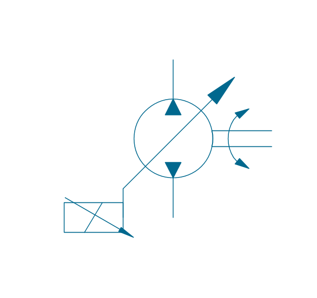
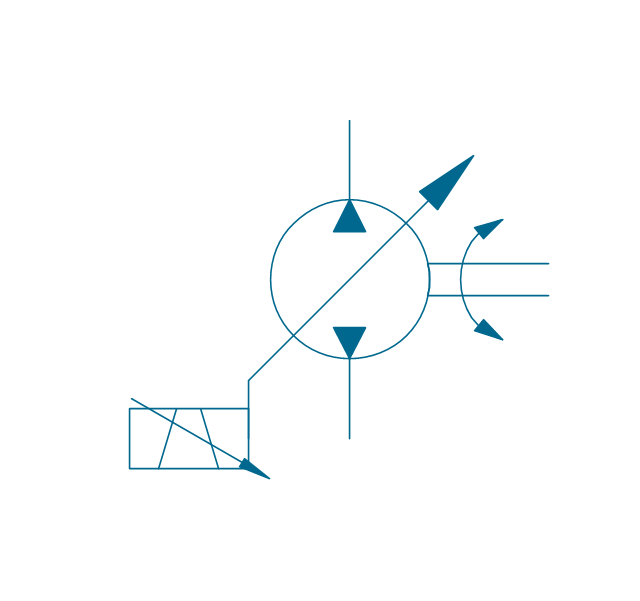
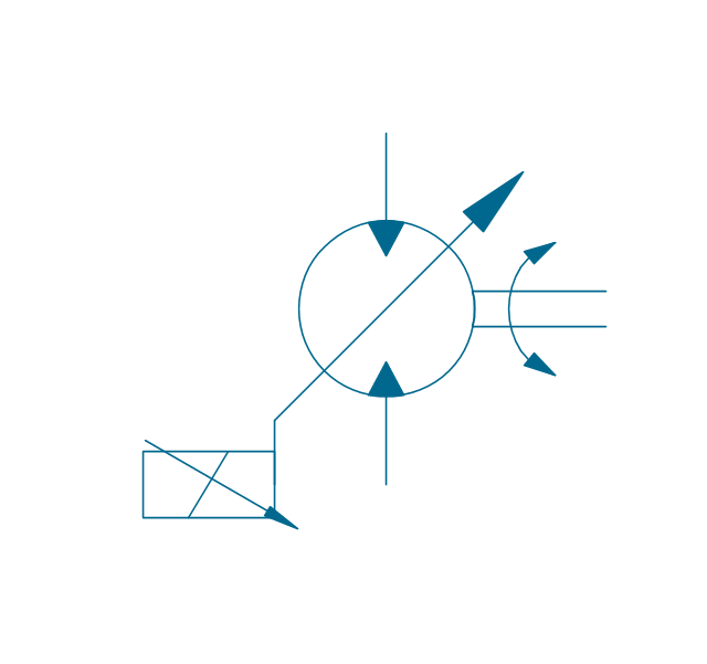
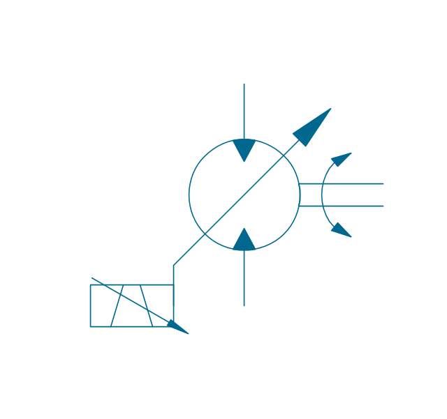
Pump, var., manual override

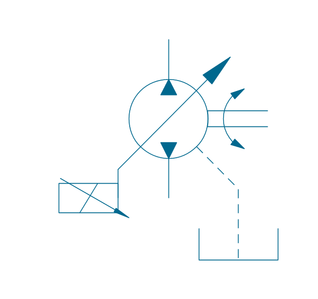
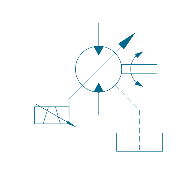
Pump, var., manual override, drain
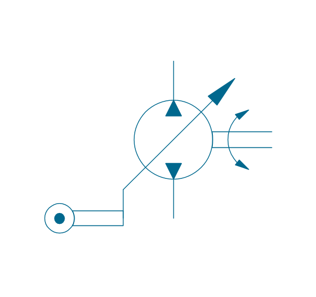
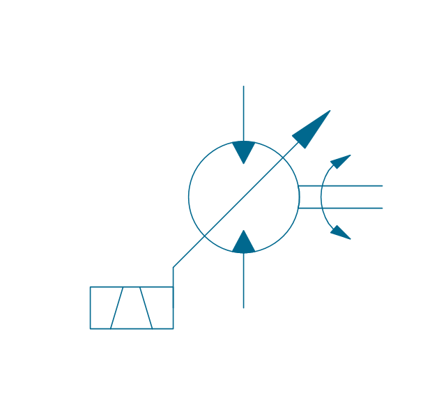
Pump, var., solenoid
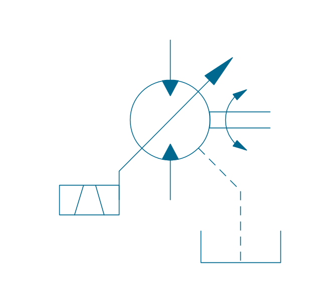
Pump, var., solenoid, drain

Pump, var., solenoid 2

Pump, var., solenoid 2, drain
Pump, var., var. solenoid
Pump, var., var. solenoid, drain
Pump, var., var. solenoid 2
Pump, var., var. solenoid 2, drain

Pump, var., var., roller
Pump, var., roller, drain
Motor, fixed, external drain
Motor, fixed, external drain
Motor, variable
Motor, variable, external drain
Motor, var., manual override
Motor, var., manual override, drain

Motor, var., solenoid

Motor, var., solenoid, drain

Motor, var., solenoid 2
Motor, var., solenoid 2, drain
Motor, var., var. solenoid
Motor, var., var. solenoid, drain

Motor, var., var. solenoid 2
Motor, var., var. solenoid 2, drain
Motor, var., var., roller
Motor, var., roller, drain
Pump-motor, fixed, external drain
Pump-motor, fixed, external drain
Pump-motor, variable
Pump-motor, variable, external drain
Pump-motor, var., manual override
Pump-motor, var., manual override, drain
Pump-motor, var., solenoid

Pump-motor, var., solenoid, drain

Pump-motor, var., solenoid 2
Pump-motor, var., solenoid 2, drain
Pump-motor, var., var. solenoid
Pump-motor, var., var. solenoid, drain

Pump-motor, var., var. solenoid 2

Pump-motor, var., var. solenoid 2, drain
Pump-motor, var., var., roller
Pump-motor, var., roller, drain
Pump, fixed 2
Pump, fixed 2, drain
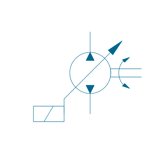
Pump, variable (sgl side)
-hydraulic-pumps-and-motors---vector-stencils-library.png--diagram-flowchart-example.png)
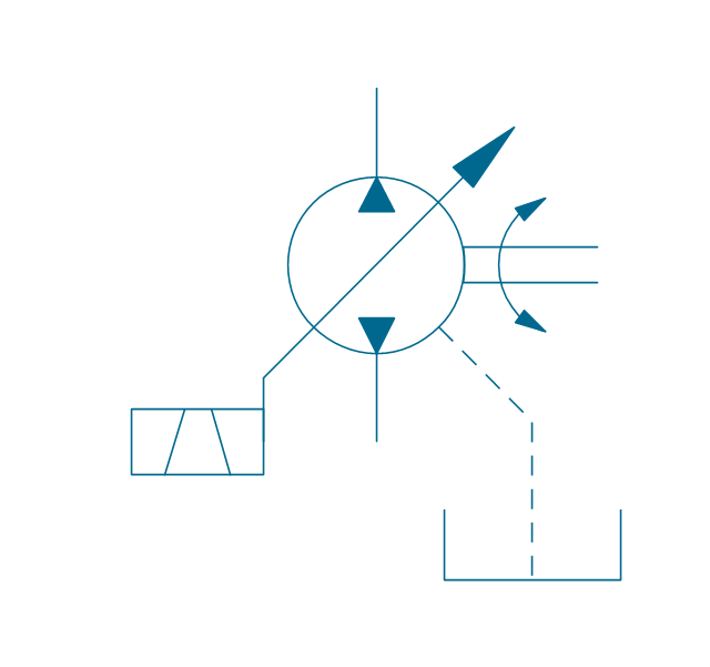
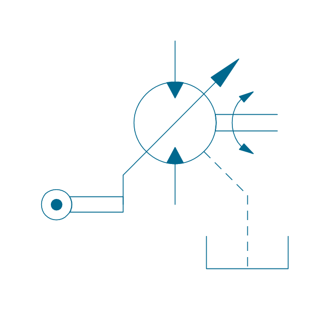
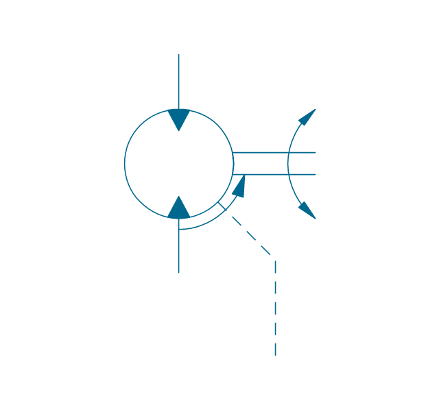
Pump, variable (sgl side), drain
,-drain-hydraulic-pumps-and-motors---vector-stencils-library.png--diagram-flowchart-example.png)
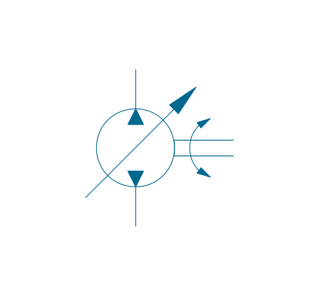
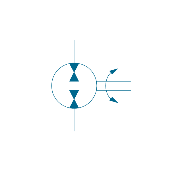
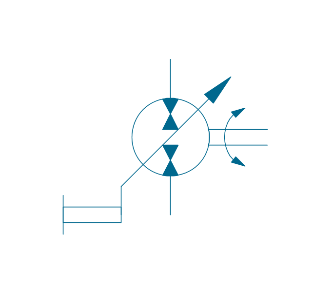
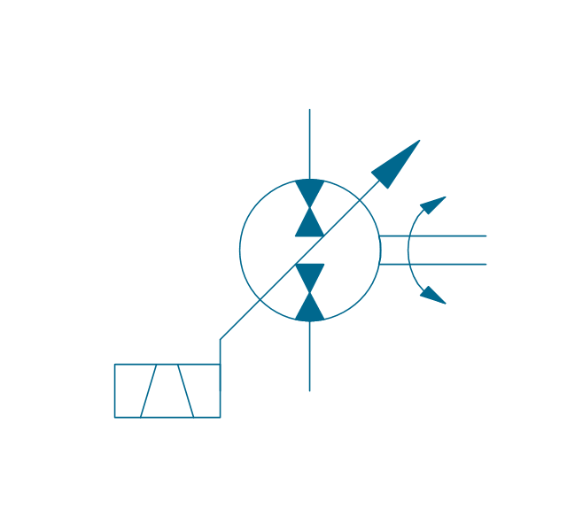
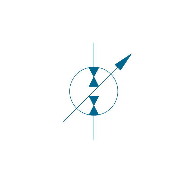
Pump, variable (dbl side)
-hydraulic-pumps-and-motors---vector-stencils-library.png--diagram-flowchart-example.png)
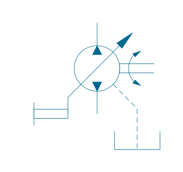
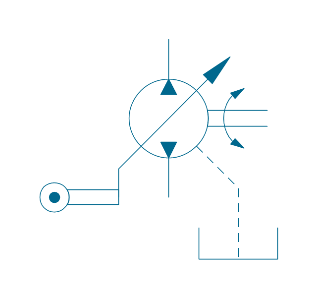
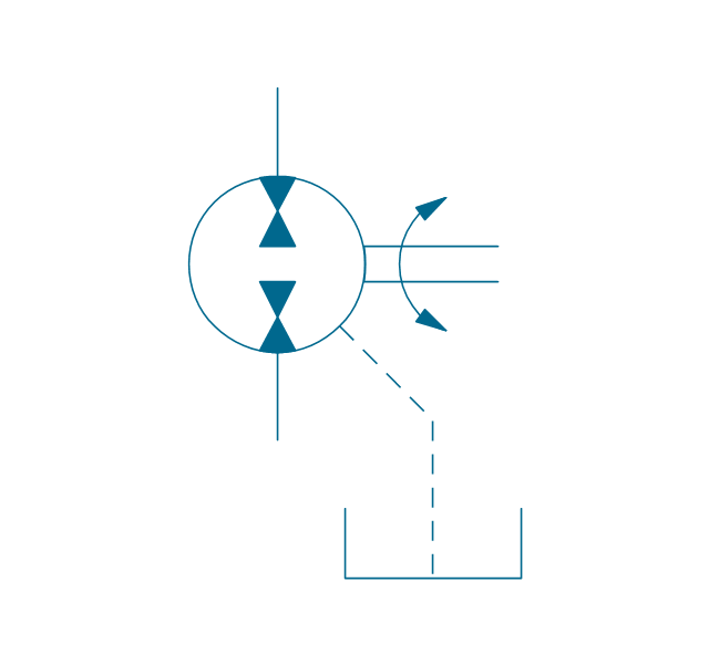
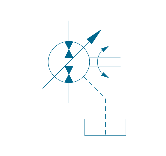
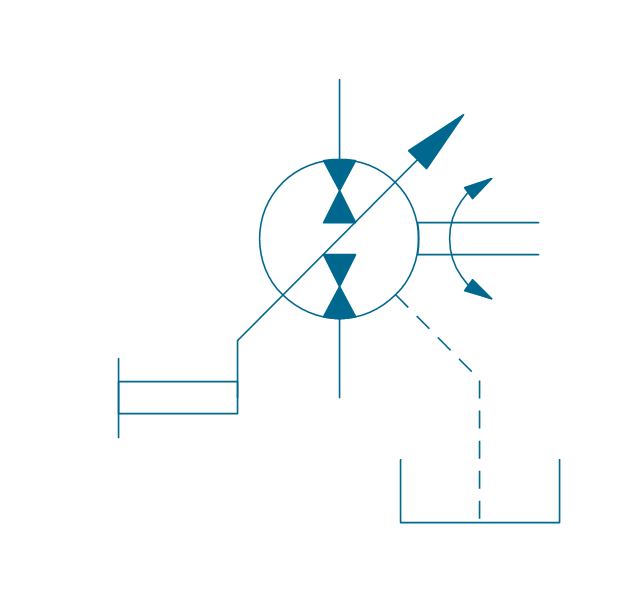
Pump, variable (dbl side), drain
,-drain-hydraulic-pumps-and-motors---vector-stencils-library.png--diagram-flowchart-example.png)
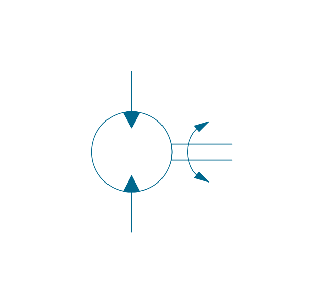
Motor, fixed 2
Motor, variable (sgl side)
-hydraulic-pumps-and-motors---vector-stencils-library.png--diagram-flowchart-example.png)
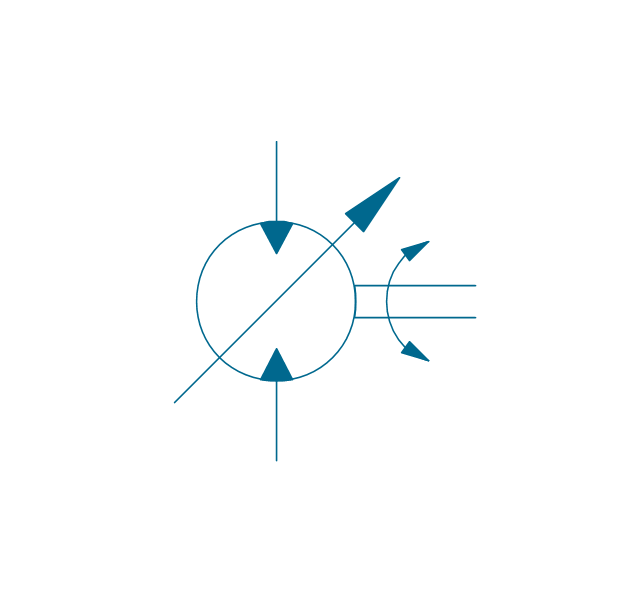
Motor, variable (dbl side)
-hydraulic-pumps-and-motors---vector-stencils-library.png--diagram-flowchart-example.png)
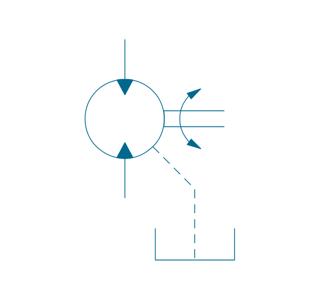
Motor, fixed 2, drain
Motor, variable (sgl side), drain
,-drain-hydraulic-pumps-and-motors---vector-stencils-library.png--diagram-flowchart-example.png)
Motor, variable (dbl side), drain
,-drain-hydraulic-pumps-and-motors---vector-stencils-library.png--diagram-flowchart-example.png)
Pump-motor, fixed 2
Pump-motor, fixed 2, drain
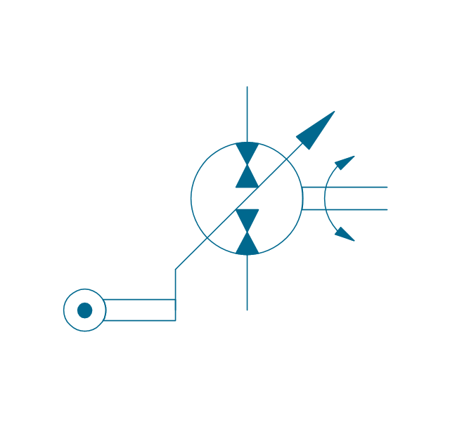
Pump-motor, variable (sgl side)
-hydraulic-pumps-and-motors---vector-stencils-library.png--diagram-flowchart-example.png)
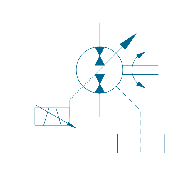
Pump-motor, variable (sgl side), drain
,-drain-hydraulic-pumps-and-motors---vector-stencils-library.png--diagram-flowchart-example.png)
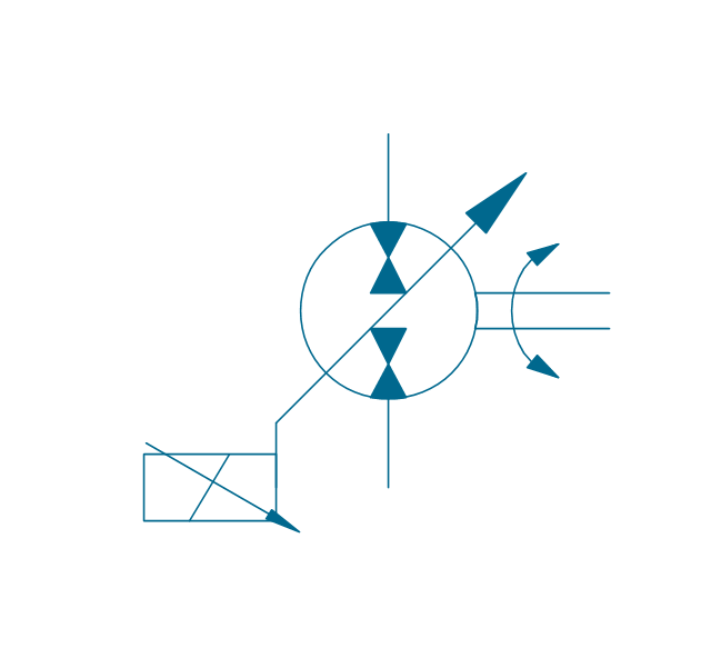
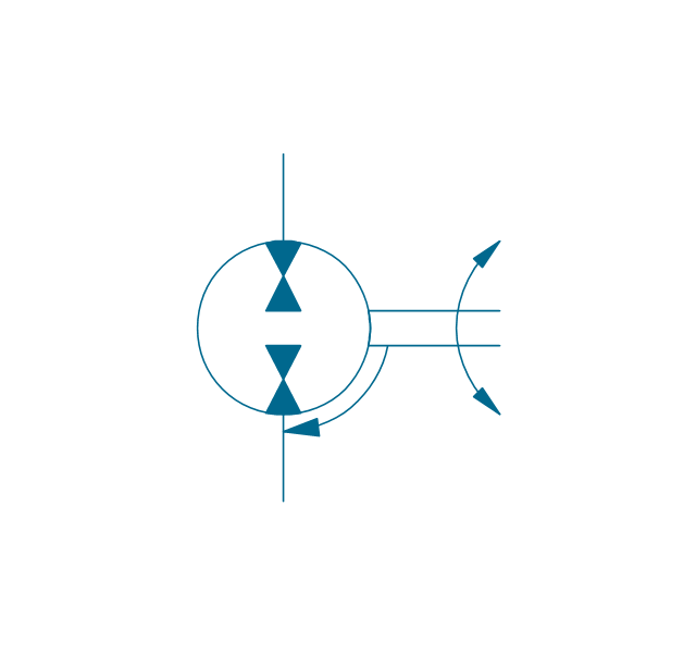
Pump-motor, variable (dbl side)
-hydraulic-pumps-and-motors---vector-stencils-library.png--diagram-flowchart-example.png)
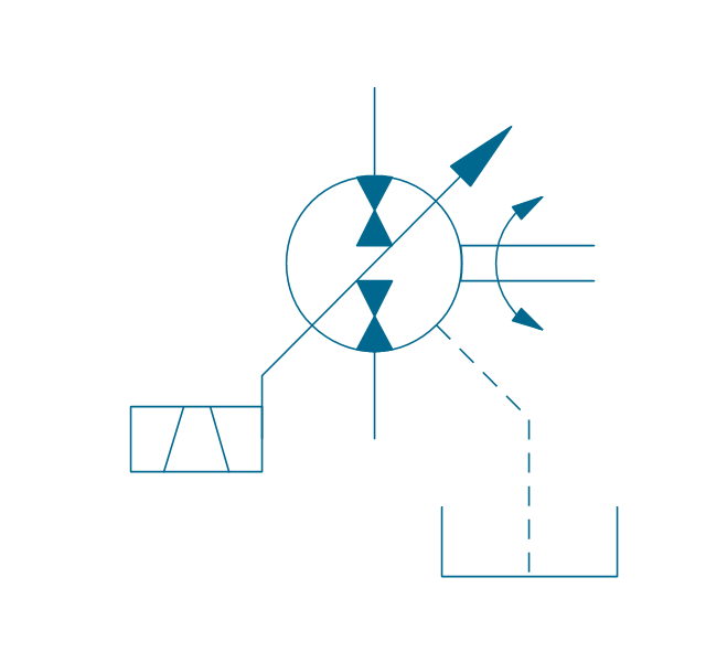
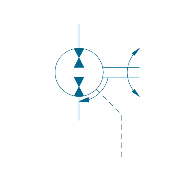
Pump-motor, variable (dbl side), drain
,-drain-hydraulic-pumps-and-motors---vector-stencils-library.png--diagram-flowchart-example.png)
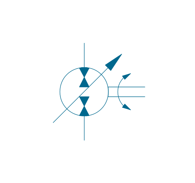
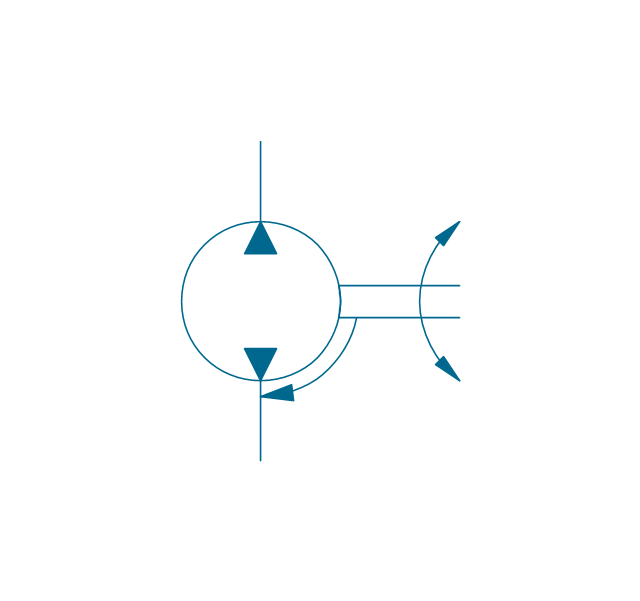
Pump, variable displacement
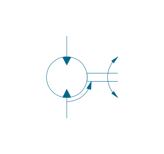
Motor, variable displacement
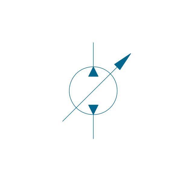
Pump-motor, variable displacement
Floating motor
Pressure compensator
Mechanical Engineering

Technical Drawing Software

Technical Drawing Software

The vector stencils library "Valve assembly" contains 141 symbols of pressure and flow regulators, flow direction indicators, controls, and symbols to design flow paths of control valves.
Use these valve assembly shapes to design the engineering drawings of hydraulic and pneumatic valve assemblies in fluid power systems.
"Control valves are valves used to control conditions such as flow, pressure, temperature, and liquid level by fully or partially opening or closing in response to signals received from controllers that compare a "setpoint" to a "process variable" whose value is provided by sensors that monitor changes in such conditions.
The opening or closing of control valves is usually done automatically by electrical, hydraulic or pneumatic actuators. Positioners are used to control the opening or closing of the actuator based on electric, or pneumatic signals.
A control valve consists of three main parts in which each part exist in several types and designs: Valve's actuator, Valve's positioner, Valve's body.
" [Control valves. Wikipedia]
The shapes example "" was created using the ConceptDraw PRO diagramming and vector drawing software extended with the Mechanical Engineering solution from the Engineering area of ConceptDraw Solution Park.
Valve assembly symbols

Building Drawing Software for Designing Plumbing


Making Mechanical Diagram

Mathematics Symbols

How To Create Emergency Plans and Fire Evacuation

The vector stencils library "Fluid power equipment" contains 113 symbols of hydraulic and pneumatic equipment including pumps, motors, air compressors, cylinders, meters, gauges, and actuators. Use it to design fluid power and hydraulic control systems.
"Fluid power is the use of fluids under pressure to generate, control, and transmit power. Fluid power is subdivided into hydraulics using a liquid such as mineral oil or water, and pneumatics using a gas such as air or other gases. Compressed-air and water-pressure systems were once used to transmit power from a central source to industrial users over extended geographic areas; fluid power systems today are usually within a single building or mobile machine." [Fluid power. Wikipedia]
The shapes example "Design elements - Fluid power equipment" was created using the ConceptDraw PRO diagramming and vector drawing software extended with the Mechanical Engineering solution from the Engineering area of ConceptDraw Solution Park.
Fluid power symbols

"Directional control valves are one of the most fundamental parts in hydraulic machinery as well and pneumatic machinery. They allow fluid flow into different paths from one or more sources. They usually consist of a spool inside a cylinder which is mechanically or electrically controlled. The movement of the spool restricts or permits the flow, thus it controls the fluid flow. ...
While working with layouts of hydraulic machinery it is cumbersome to draw actual picture of every valve and other components.instead of pictures symbols are used for variety of components in the hydraulic system to highlight the functional aspects. symbol for directional control valve is made of number of square boxes adjacent to each other depending on the number of positions.connections to the valve are shown on these squares by capital letters.usually they are named only in their normal position and not repeated in other positions.actuation system of the valve is also designated in its symbol." [Directional control valve. Wikipedia]
The Mac template "Pneumatic 5-ported 3-position valve" for the ConceptDraw PRO diagramming and vector drawing software is included in the Mechanical Engineering solution from the Engineering area of ConceptDraw Solution Park.
www.conceptdraw.com/ solution-park/ engineering-mechanical
Pneumatic directional control valve

The vector stencils library "Fluid power valves" contains 93 symbols of pre-made hydraulic and pneumatic valves, including directional control valves, flow control valves, pressure control valves, and electrohydraulic and electropneumatic valves.
"Control valves are valves used to control conditions such as flow, pressure, temperature, and liquid level by fully or partially opening or closing in response to signals received from controllers that compare a "setpoint" to a "process variable" whose value is provided by sensors that monitor changes in such conditions.
The opening or closing of control valves is usually done automatically by electrical, hydraulic or pneumatic actuators. Positioners are used to control the opening or closing of the actuator based on electric, or pneumatic signals.
A control valve consists of three main parts in which each part exist in several types and designs: Valve's actuator, Valve's positioner, Valve's body.
" [Control valves. Wikipedia]
The shapes example "Design elements - Fluid power valves" was created using the ConceptDraw PRO diagramming and vector drawing software extended with the Mechanical Engineering solution from the Engineering area of ConceptDraw Solution Park.
Fluid power valve symbols

The vector stencils library "Fluid power equipment" contains 113 symbols of hydraulic and pneumatic equipment including pumps, motors, air compressors, cylinders, meters, gauges, and actuators.
Use it to design fluid power and hydraulic control systems in the ConceptDraw PRO diagramming and vector drawing software extended with the Mechanical Engineering solution from the Engineering area of ConceptDraw Solution Park.
www.conceptdraw.com/ solution-park/ engineering-mechanical
Use it to design fluid power and hydraulic control systems in the ConceptDraw PRO diagramming and vector drawing software extended with the Mechanical Engineering solution from the Engineering area of ConceptDraw Solution Park.
www.conceptdraw.com/ solution-park/ engineering-mechanical
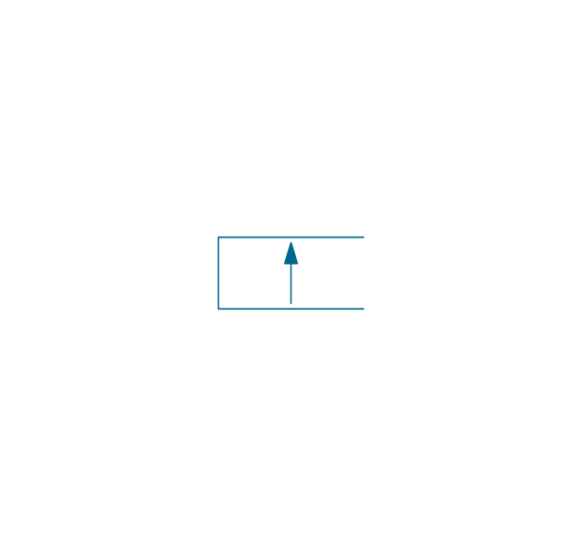
Actuator (semi-rotary), pneumatic
,-pneumatic-fluid-power-equipment---vector-stencils-library.png--diagram-flowchart-example.png)
Actuator (semi-rotary), hydraulic
,-hydraulic-fluid-power-equipment---vector-stencils-library.png--diagram-flowchart-example.png)
Drive unit, pneumatic

Drive unit, hydraulic

Sgl-act. cylinder, pneum., left spring

Sgl-act. cylinder, pneum., right spring

Sgl-act. cylinder, pneumatic

Sgl-act. cylinder, hydr., left spring

Sgl-act. cylinder, hydr., right spring

Sgl-act. cylinder, hydraulic

Dbl-act. cylinder, pneumatic

Dbl-act. cylinder, pneum., sgl cushion

Dbl-act. cylinder, pneum., dbl cushion

Dbl-act. cylinder, pneum., adjustable

Dbl-act. cylinder, pneum., sgl cushion, adj.

Dbl-act. cylinder, pneum., dbl cushion, adj.

Dbl-act. cylinder, hydraulic

Dbl-act. cylinder, hydr., sgl cushion

Dbl-act. cylinder, hydr., dbl cushion

Dbl-act. cylinder, hydr., adjustable

Dbl-act. cylinder, hydr., sgl cushion, adj.

Dbl-act. cylinder, hydr., dbl cushion, adj.

Dbl-act. cylinder, magnetic

Dbl-act. cylinder, magn., sgl cushion

Dbl-act. cylinder, magn., dbl cushion

Dbl-act. cylinder, magn., adjustable

Dbl-act. cylinder, magn., sgl cushion, adj.

Dbl-act. cylinder, magn., dbl cushion, adj.

Dbl-act. dbl-end. cylinder, pneumatic

Dbl-act. dbl-end. cylinder, pneum., sgl cushion

Dbl-act. dbl-end. cylinder, pneum., dbl cushion

Dbl-act. dbl-end. cylinder, pneum., adjustable

Dbl-act. dbl-end. cylinder, pneum., sgl cushion, adj.

Dbl-act. dbl-end. cylinder, pneum., dbl cushion, adj.

Dbl-act. dbl-end. cylinder, hydraulic

Dbl-act. dbl-end. cylinder, hydr., sgl cushion

Dbl-act. dbl-end. cylinder, hydr., dbl cushion

Dbl-act. dbl-end. cylinder, hydr., adjustable

Dbl-act. dbl-end. cylinder, hydr., sgl cushion, adj.

Dbl-act. dbl-end. cylinder, hydr., dbl cushion, adj.

Telescopic cylinder, pneum., dbl-act.

Telescopic cylinder, hydr., dbl-act.

Telescopic cylinder, pneum., sgl-act.

Telescopic cylinder, hydr., sgl-act.

Actuator, hydraulic-pneumatic

Actuator, pneumatic-hydraulic

Intensifier, pneumatic

Intensifier, hydraulic

Intensifier, hydraulic-pneumatic

Intensifier, pneumatic-hydraulic

Intensifier, pneumatic-hydraulic

Intensifier, hydraulic-pneumatic

Actuator, pneumatic-hydraulic

Actuator, hydraulic-pneumatic

Accumulator

Accumulator, gas loaded

Accumulator, spring loaded

Accumulator, auxiliary gas bottle

Air receiver

Energy source, pneumatic

Energy source, hydraulic

Energy source, electric motor

Energy source, non-electric prime mover

Vented reservoir

Sealed reservoir

Filter

Filter, magnetic element

Filter, contamination indicator

Automatic drain filter separator

Manual drain filter separator

Separator, automatic drain

Separator, manual drain

Air dryer

Lubricator

Air service unit, filter, separator

Air service unit, separator

Air service unit, filter

Air service unit

Liquid cooler

Gas cooler

Cooler

Liquid heater

Gas heater

Heater

Liquid temperature controller

Gas temperature controller

Temperature controller

Liquid temperature controller 2

Gas temperature controller 2

Temperature controller 2

Pressure indicator

Pressure gauge

Differential pressure gauge

Thermometer

Liquid level measuring instrument

Flow indicator

Flow meter

Integrating flow meter

Tachometer

Torque measurement equipment

Pressure switch

Limit switch

Transducer

Pulse counter

Pulse counter 2

Silencer

Drain (inlet below fluid, drain line)
-fluid-power-equipment---vector-stencils-library.png--diagram-flowchart-example.png)
Drain (inlet below fluid, return line)
-fluid-power-equipment---vector-stencils-library.png--diagram-flowchart-example.png)
Drain (inlet above fluid, drain line)
-fluid-power-equipment---vector-stencils-library.png--diagram-flowchart-example.png)
Drain (inlet above fluid, return line)
-fluid-power-equipment---vector-stencils-library.png--diagram-flowchart-example.png)
Oil tank

Oil tank, empty

Air compressor

Building Drawing. Design Element: Piping Plan

Process Flow Diagram Symbols

- Mechanical Drawing Symbols | Mechanical Design Software ...
- Mechanical Drawing Symbols | Engineering | Technical Drawing ...
- Mechanical Drawing Symbols | Mechanical Engineering ...
- Mechanical Drawing Symbols | Design elements - Fluid power ...
- Design elements - Hydraulic pumps and motors | Electrical Symbols ...
- Mechanical Engineering | Pipes 2 - Vector stencils library ...
- Mechanical Engineering | Draw Hydraulic Circuit For A Hydraulic ...
- Design elements - Hydraulic pumps and motors | Mechanical ...
- Mechanical Drawing Symbols | Design elements - Hydraulic pumps ...
- Mechanical Drawing Symbols | Mechanical Engineering ...
- Mechanical Drawing Symbols | Home Electrical Plan | Electrical ...
- Mechanical Drawing Symbols | Process Flow Diagram Symbols ...
- Mechanical Drawing Symbols | Process Flow Diagram Symbols ...
- Mechanical Drawing Symbols | Design elements - Hydraulic pumps ...
- Mechanical Drawing Symbols | Technical Drawing Software ...
- Mechanical Drawing Symbols | Home Electrical Plan | Process Flow ...
- Engineering | Mechanical Engineering | Apparatus for testing the ...
- Mechanical Drawing Symbols | Engineering | Technical Drawing ...
- Technical Drawing Software | Mechanical Engineering | Mechanical ...