 Electric and Telecom Plans
This solution extends ConceptDraw PRO software with samples, templates and libraries of vector stencils for drawing the Electric and Telecom Plans.
HelpDesk
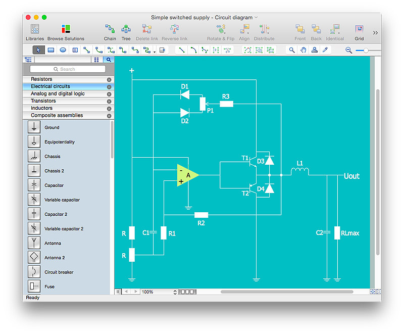
How to Create an Electrical Diagram Using ConceptDraw PRO
There are many of different electric circuit symbols that can be used in a circuit diagram. Knowing how to read circuit diagrams is a useful skill not only for professionals, but for any person who can start creating his own small home electronic projects. The circuit diagram shows the scheme of a location of components and connections of the electrical circuit using a set of standard symbols. It can be use for graphical documentation of an electrical circuit components. The ability to create electrical diagrams and schematic using ConceptDraw PRO is delivered by the Electrical Engineering solution. The solution supplied with samples, templates and libraries of design elements for drawing electrical schematics, digital and analog logic, circuit and wiring schematics and diagrams, power systems diagrams, maintenance and repair diagrams for electronics and electrical engineering.
 ConceptDraw Solution Park
ConceptDraw Solution Park collects graphic extensions, examples and learning materials
HelpDesk
How to Draw an Electrical Scheme Using ConceptDraw Solution Park
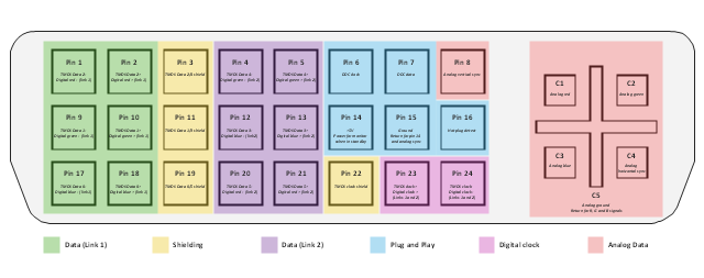
The ability to visualize industrial systems in electronics, electrical, chemical, process, and mechanical engineering is delivered by the ConceptDraw Engineering solution.This AV connector pinout diagram example was redesigned from the file: DVI pinout.svg. [en.wikipedia.org/ wiki/ File:DVI_ pinout.svg]
"In electronics, a pinout (sometimes written "pin-out") is a cross-reference between the contacts, or pins, of an electrical connector or electronic component, and their functions. ...
The functions of contacts in electrical connectors, be they power- or signaling-related, must be specified in order for connectors to be interchangeable. When connected, each contact of a connector must mate with the contact on the other connector that has the same function. If contacts of disparate functions are allowed to make contact, the connection may fail and damage may result. Therefore, pinouts are a vital reference when building and testing connectors, cables, and adapters." [Pinout. Wikipedia]
The example "DVI pinout diagram" was created using the ConceptDraw PRO diagramming and vector drawing software extended with the Audio and Video Connectors solution from the Engineering area of ConceptDraw Solution Park.
 Network Layout Floor Plans
Network Layout Floor Plan solution extends ConceptDraw PR software with samples, templates and libraries of vector stencils for drawing the computer network layout floor plans.
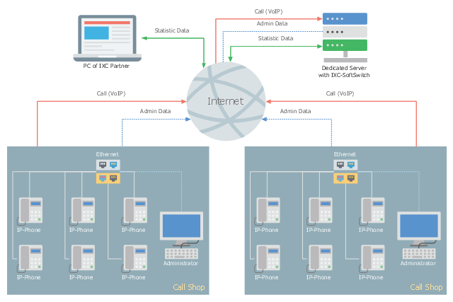
This telecom diagram sample illustrates the call shop solution. It was designed on the base of the Wikimedia Commons file: Call shops.jpg.
[commons.wikimedia.org/ wiki/ File:Call_ shops.jpg]
This file is licensed under the Creative Commons Attribution-Share Alike 3.0 Unported license. [creativecommons.org/ licenses/ by-sa/ 3.0/ deed.en]
"A call shop is a business providing on-site access to telephones for long-distance calling in countries without widespread home long-distance service. Calls may be prepaid or postpaid." [Call shop. Wikipedia]
The telecommunication diagram example "Call shop solution" was created using the ConceptDraw PRO diagramming and vector drawing software extended with the Computers and Communications solution from the Illustration area of ConceptDraw Solution Park.
 Engineering
This solution extends ConceptDraw PRO v9.4 with the ability to visualize industrial systems in electronics, electrical, chemical, process, and mechanical engineering.
 Event-driven Process Chain Diagrams
Event-driven Process Chain (EPC) Diagram is a type of flowchart widely used for modeling in business engineering and reengineering, business process improvement, and analysis. EPC method was developed within the Architecture of Integrated Information Systems (ARIS) framework.
- Electrical Drawing Software | How To use House Electrical Plan ...
- How To use House Electrical Plan Software | Cafe electrical floor ...
- Electrical Wiring Design Software
- How To use House Electrical Plan Software | Electrical Drawing ...
- How To use House Electrical Plan Software | Electrical Drawing ...
- Wiring Diagrams with ConceptDraw PRO | Wiring Diagram Floor ...
- Wiring Diagrams with ConceptDraw PRO | Wiring Diagram Floor ...
- How To use House Electrical Plan Software | Electrical Diagram ...
- How To use House Electrical Plan Software | Electrical Diagram ...
- How To use House Electrical Plan Software | Wiring Diagram Floor ...
- Wiring Diagrams with ConceptDraw PRO | How To use House ...
- How To use House Electrical Plan Software | Electrical Drawing ...
- Design elements - Electrical circuits | Electrical Diagram Symbols ...
- Design elements - Electrical and telecom | Electrical Diagram ...
- Engineering | Wiring Diagrams with ConceptDraw PRO | How To ...
- Electrical Plug Symbol
- Wiring Diagram Floor Software | How To use House Electrical Plan ...
- Home area network (HAN) wiring diagram | How To use House ...
- Engineering | Technical Drawing Software | Electrical Diagram ...
- How To use House Electrical Plan Software | Electrical Diagram ...


