 Fault Tree Analysis Diagrams
This solution extends ConceptDraw PRO v9.5 or later with templates, fault tree analysis example, samples and a library of vector design elements for drawing FTA diagrams (or negative analytical trees), cause and effect diagrams and fault tree diagrams.
Data structure diagram with ConceptDraw PRO
Data structure diagram (DSD) is intended for description of conceptual models of data (concepts and connections between them) in the graphic format for more obviousness. Data structure diagram includes entities description, connections between them and obligatory conditions and requirements which connect them. Create Data structure diagram with ConceptDraw PRO.HelpDesk
How to Create a Fault Tree Analysis Diagram (FTD) in ConceptDraw PRO
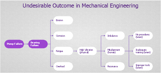
Fault Tree Diagram are logic diagram that shows the state of an entire system in a relationship of the conditions of its elements. Fault Tree Diagram are used to analyze the probability of functional system failures and safety accidents. ConceptDraw PRO allows you to create professional Fault Tree Diagrams using the basic FTD symbols. An FTD visualize a model of the processes within a system that can lead to the unlikely event. A fault tree diagrams are created using standard logic symbols . The basic elements in a fault tree diagram are gates and events."Root cause analysis (RCA) is a method of problem solving that tries to identify the root causes of faults or problems.
RCA practice tries to solve problems by attempting to identify and correct the root causes of events, as opposed to simply addressing their symptoms. Focusing correction on root causes has the goal of preventing problem recurrence. RCFA (Root Cause Failure Analysis) recognizes that complete prevention of recurrence by one corrective action is not always possible.
Conversely, there may be several effective measures (methods) that address the root causes of a problem. Thus, RCA is an iterative process and a tool of continuous improvement.
RCA is typically used as a reactive method of identifying event(s) causes, revealing problems and solving them. Analysis is done after an event has occurred. Insights in RCA may make it useful as a preemptive method. In that event, RCA can be used to forecast or predict probable events even before they occur. While one follows the other, RCA is a completely separate process to Incident Management." [Root cause analysis. Wikipedia]
The root cause analysis (RCA) tree diagram example "Manufacturing problem solution" was created using the ConceptDraw PRO diagramming and vector drawing software extended with the solution "Seven Management and Planning Tools" from the Management area of ConceptDraw Solution Park.
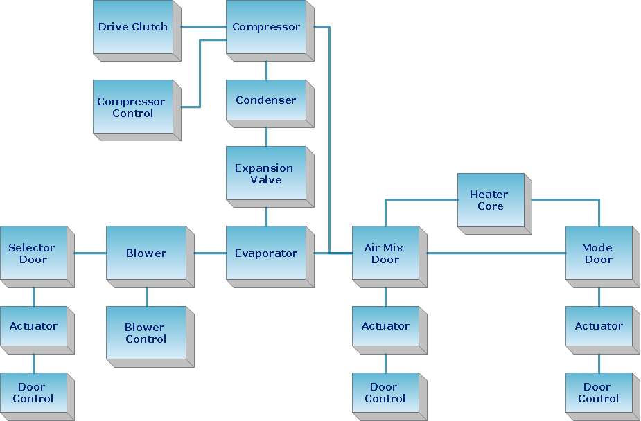
 Block Diagrams
Block diagrams solution extends ConceptDraw PRO software with templates, samples and libraries of vector stencils for drawing the block diagrams.
ConceptDraw Arrows10 Technology
How should diagramming software work? The answer is - Fast and easy. "Tree"- mode drawing works like that. Just select objects in your drawing and press Tree or Chain button to connect all of them just in one click. Your diagram looks professional and it took only a moment to draw.
 Interactive Voice Response Diagrams
Interactive Voice Response Diagrams solution extends ConceptDraw PRO v10 software with samples, templates and libraries of ready-to-use vector stencils that help create Interactive Voice Response (IVR) diagrams illustrating in details a work of interactive voice response system, the IVR system’s logical and physical structure, Voice-over-Internet Protocol (VoIP) diagrams, and Action VoIP diagrams with representing voice actions on them, to visualize how the computers interact with callers through voice recognition and dual-tone multi-frequency signaling (DTMF) keypad inputs.
- Fault Tree Analysis Diagrams | PROBLEM ANALYSIS. Root Cause ...
- Root cause analysis tree diagram - Template
- FTA diagram - Hazard analysis | Accident analytic tree - FTA ...
- Example Of Tree Or Stream Chart
- Decision tree diagram | Marketing Charts | Marketing Diagrams ...
- Fault Tree Analysis Diagrams | Fault Tree Analysis Example | Fault ...
- Fault Tree Analysis Diagrams | Fishbone Diagram | Fishbone ...
- Fault Tree Analysis Diagrams | Seven Management and Planning ...
- Fault Tree Analysis Diagrams
- PROBLEM ANALYSIS. Root Cause Analysis Tree Diagram | TQM ...
- Marketing Analysis Diagram | Process Flowchart | Fault Tree ...
- Fault Tree Analysis Example | Fault Tree Analysis Diagrams | How to ...
- Fault Tree Analysis Example | Fault Tree Diagram | Fault Tree ...
- Tree Network Topology Diagram | Fault Tree Analysis Example ...
- Fault Tree Analysis Diagrams | Fault Tree Analysis Example | How to ...
- Active Directory Diagram | Tree and Forest (Full Trust) - Active ...
- Fault Tree Analysis Visio Sample
- Fault Tree Diagram | Fault Tree Analysis Example | Fault Tree ...
- Cause and Effect Analysis | PROBLEM ANALYSIS. Root Cause ...


