How To use House Electrical Plan Software


Standard Universal Audio & Video Connection Types

The vector stencils library "Electrical and telecom" contains 83 symbols of electrical and telecommunication equipment.
Use these shapes for drawing electrical and telecom system design floor plans, cabling layout schemes, and wiring diagrams in the ConceptDraw PRO diagramming and vector drawing software.
The vector stencils library "Electrical and telecom" is included in the Electric and Telecom Plans solution from the Building Plans area of ConceptDraw Solution Park.
Luminaire ceiling mount

Enclosed ceiling luminaire

Wall light

1-light bar

2-light bar

4-light bar

6-light bar

8-light bar

Down lighter

Outdoor lightning

Outdoor lightning, bollard

Batten fluorescent, 1 lamp

Batten fluorescent, 2 lamps

Batten fluorescent, 3 lamps

Batten fluorescent, 4 lamps

Surface Fluorescent Light

Modular fluorescent fitting

Modular fluorescent fitting, inverter

Modular fluorescent fitting 2

Pull-cord switch

Emergency light

Emergency light 2

Emergency sign

Switch

Switch, 1 pole

Switch, 2 pole

Switch, 2-way

Multi-switch

Switch, intermediate

Dimmer switch

Dimmer switch 2

Socket

Socket 2

Switched socket

Switched socket 2

Double socket

Double socket 2

Socket outlet

Telephone outlet

Telephone outlet 2

Stereo outlet

Television outlet

Service panel, surface

Service panel, inset

Thermostat

Ceiling fan

Hold open unit

Detector

Fire alarm

City Fire Alarm Station

Fire Alarm Station

Fire Alarm Bell

Fire Alarm Central Station

Automatic Fire Alarm Device

Main control

Ground

Doorbell

Push Button

Buzzer

Annunciator

Horn

Maid's Signal Plug

Signal Central Station

Doorbell Chime

Doorbell Transformer

Magnetic Door Hold

Intercom

Telephone Key System

Digital Satellite System

Inside Antenna

Outside Antenna

Electric Motors

Single Phase

Three of Poly Phase

Wall Mounted Electrical Junction Box for Hardware

Wall Mounted Telephone/Data Junction Box for Hardware

Card Reader Access System

Emergency Release Button

Motion Sensor

Electric Door Opener

Watchman's Station

Watchman's Central Station

Battery

The vector stencils library "Audio and video connectors" contains 94 symbols of audio and video connectors and device silhouettes.
Use these jacks and plugs clipart icons for drawing hook up diagrams in the ConceptDraw PRO diagramming and vector drawing software extended with the Audio and Video Connectors solution from the Engineering area of ConceptDraw Solution Park.
www.conceptdraw.com/ solution-park/ engineering-audio-video-connectors
Device 1

Device 2

TV

Cable, thin

Cable, thick

Device 1, half part

Device 2, half part

TRS plug, purple
TRS plug, brown
TRS plug, black

TRS plug, gray
TRS plug, blue
TRS plug, green
TRS jack, purple

TRS jack, brown

TRS jack, black

TRS jack, gray

TRS jack, blue

TRS jack, green

TRS plug, micro-jack
TRS, micro-jack

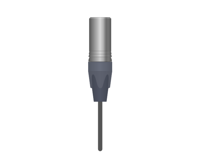
Headphone Mini Jack Cable
Headphone Mini Jack

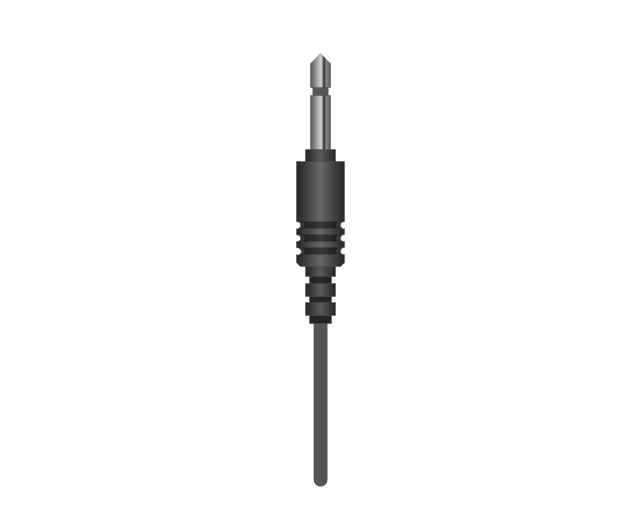
Microphone Mini Jack Cable
Microphone Mini Jack

XLR female Neutrik
XLR female Neutrik

TOSLINK Optical Audio Cable, blue
TOSLINK Optical Audio Cable
TOSLINK Optical jack
TOSLINK Optical jack, blue

DVI plug
DVI-I (Single Link) jack
-jack-audio-and-video-connectors---vector-stencils-library.png--diagram-flowchart-example.png)
DVI-I (Dual Link) jack
-jack-audio-and-video-connectors---vector-stencils-library.png--diagram-flowchart-example.png)
DVI-D (Single Link) jack
-jack-audio-and-video-connectors---vector-stencils-library.png--diagram-flowchart-example.png)
DVI-D (Dual Link) jack
-jack-audio-and-video-connectors---vector-stencils-library.png--diagram-flowchart-example.png)
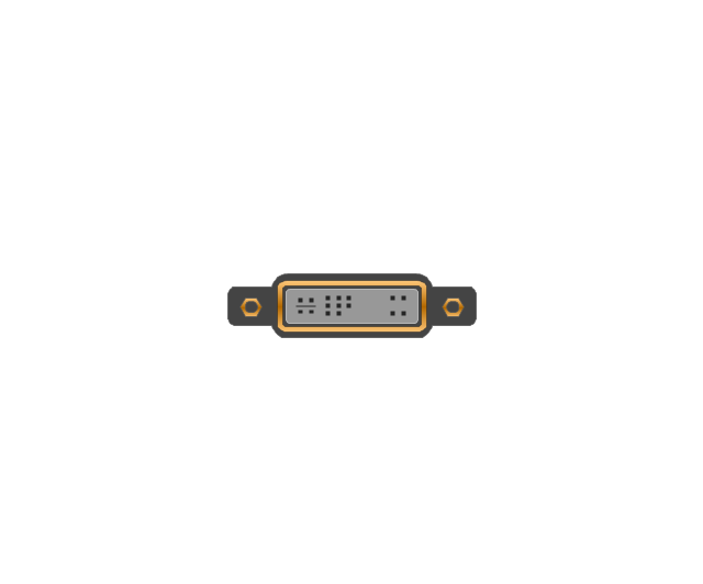
DVI-A Port
DVI-I (Single Link)
-audio-and-video-connectors---vector-stencils-library.png--diagram-flowchart-example.png)
DVI-I (Dual Link)
-audio-and-video-connectors---vector-stencils-library.png--diagram-flowchart-example.png)
DVI-D (Single Link)
-audio-and-video-connectors---vector-stencils-library.png--diagram-flowchart-example.png)
DVI-D (Dual Link)
-audio-and-video-connectors---vector-stencils-library.png--diagram-flowchart-example.png)
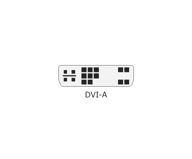
DVI-A
Mini DVI jack
Mini DVI plug
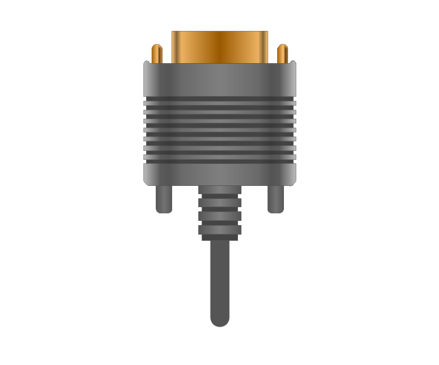
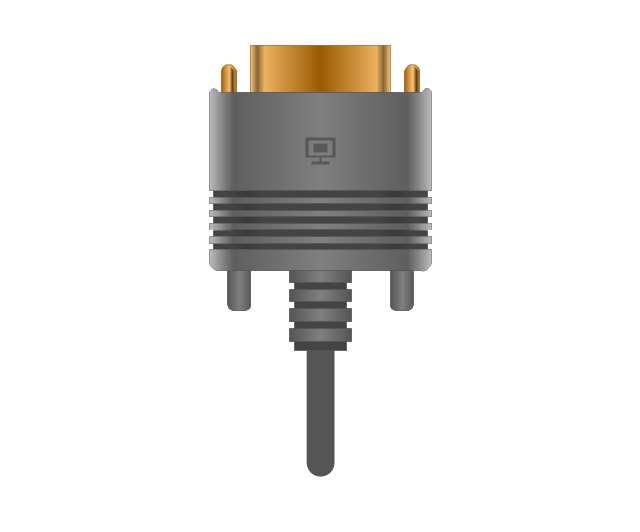
VGA plug
VGA jack
DFP jack
DFP plug
S-Video plug
S-Video IN

S-Video OUT

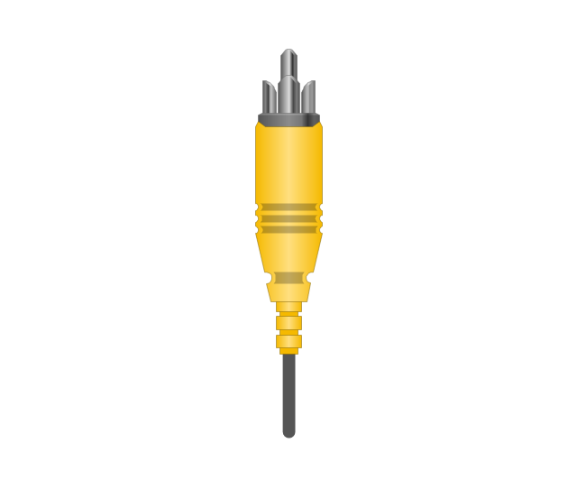
RCA, yellow

RCA, yellow
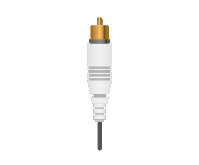
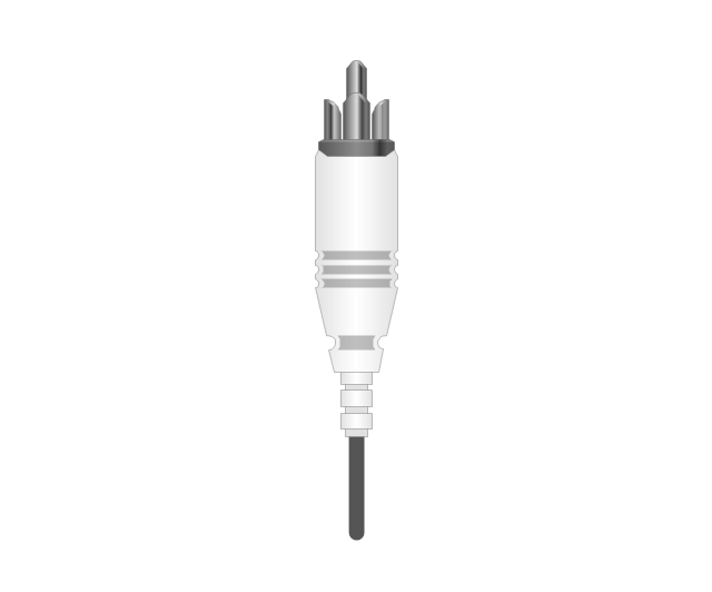
RCA, white

RCA, white
RCA, red

RCA, red

RCA, black

RCA, black
RCA, green

RCA, green
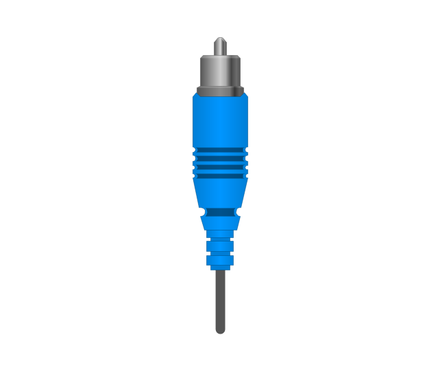
RCA, blue

RCA, blue
RCA, gray

RCA, gray
RCA, brown

RCA, brown
RCA, tan

RCA, tan
RCA, purple
RCA, purple

RCA, orange

RCA, orange
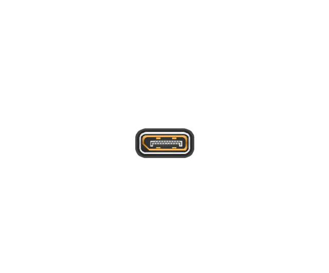
Display Port socket
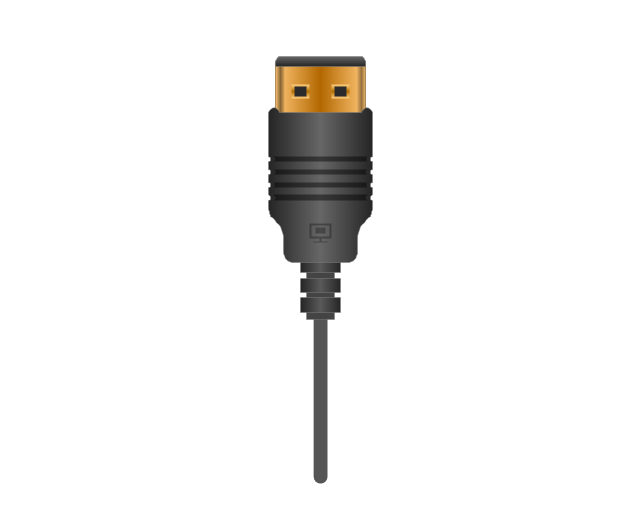
Display Port plug
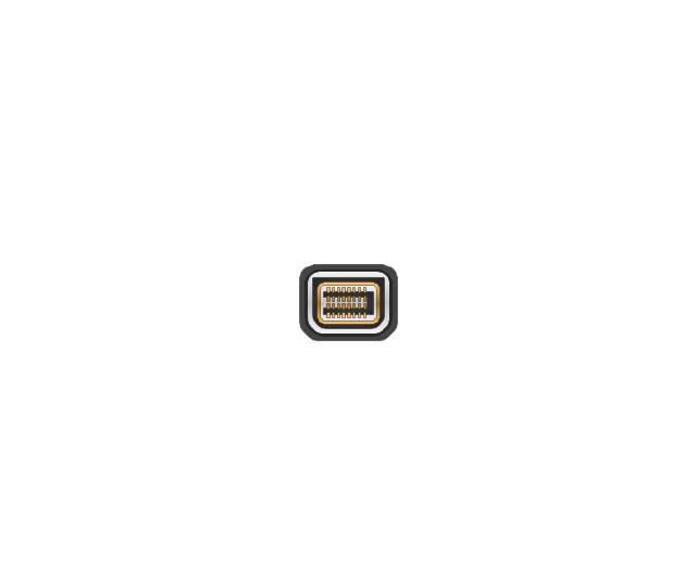
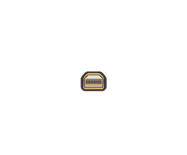
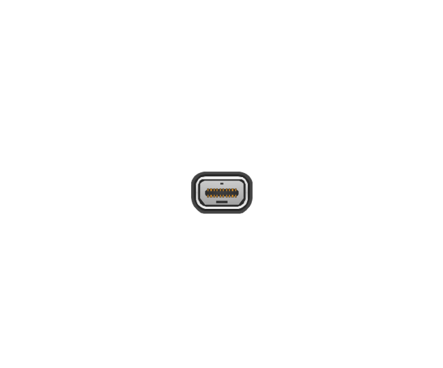
Mini Display port socket
Mini Display port socket, white

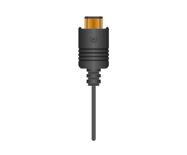
Mini Display port plug
Mini Display port plug, white
HDMI jack
HDMI plug
HDMI plug, white
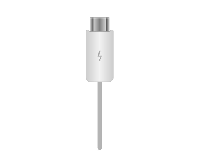
Thunderbolt jack
Thunderbolt plug
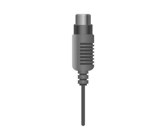
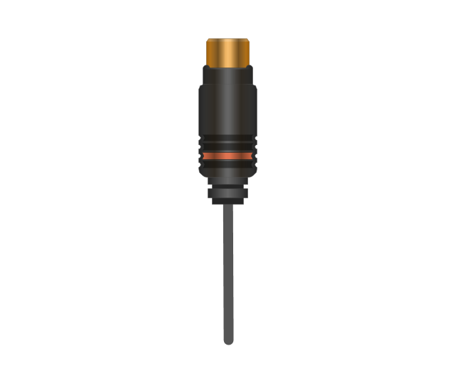
Coaxial TV plug
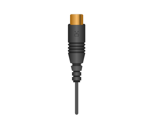
Coaxial TV jack

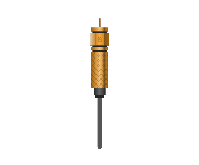
F connector jack

F connector plug
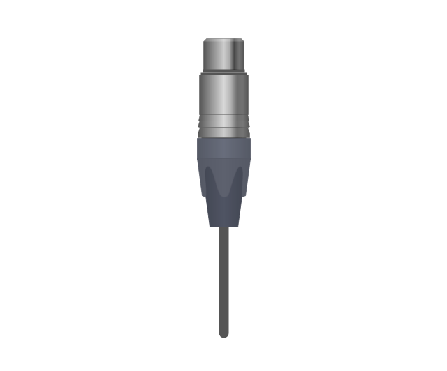
XLR male Neutrik

XLR male Neutrik
TS plug
TS jack

MIDI

MIDI
Audio Visual Connectors Types

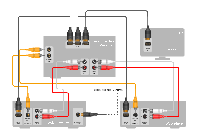
"Surround sound is a technique for enriching the sound reproduction quality of an audio source with additional audio channels from speakers that surround the listener (surround channels), providing sound from a 360° radius in the horizontal plane (2D) as opposed to "screen channels" (centre, [front] left, and [front] right) originating only from the listener's forward arc.
Surround sound is characterized by a listener location or sweet spot where the audio effects work best, and presents a fixed or forward perspective of the sound field to the listener at this location. The technique enhances the perception of sound spatialization by exploiting sound localization; a listener's ability to identify the location or origin of a detected sound in direction and distance. Typically this is achieved by using multiple discrete audio channels routed to an array of loudspeakers.
There are various surround sound based formats and techniques, varying in reproduction and recording methods along with the number and positioning of additional channels." [Surround sound. Wikipedia]
The hookup diagram example "Hook up drawing - Home entertainment system with surround sound" was created using the ConceptDraw PRO diagramming and vector drawing software extended with the Audio and Video Connectors solution from the Engineering area of ConceptDraw Solution Park.
Hookup diagram
The vector stencils library "Audio and video connectors" contains 94 symbols of audio and video connectors (TRS, TS, XLR, microphone, headphone, TOSLINK, DVI, VGA, DFP, S-Video, RCA, display port, HDMI, Thunderbolt, coaxial TV, F connector, MIDI) and device silhouettes.
Use these jacks and plugs clipart icons for drawing hook up diagrams.
"Audio connectors and video connectors are electrical connectors (or optical connectors) for carrying audio signal and video signal, of either analog or digital format. Analog A/ V connectors often use shielded cables to inhibit radio frequency interference (RFI) and noise." [Audio and video connector. Wikipedia]
"The existence of many different audio and video standards necessitates the definition of hardware interfaces, which define the physical characteristics of the connections between electrical equipment. This includes the types and numbers of wires required along with the strength and frequency of the signal. It also includes the physical design of the plugs and sockets.
An interface may define a connector that is used only by that interface (e.g., DVI) or may define a connector that is also used by another interface; for example, RCA connectors are defined both by the composite video and component video interfaces.
Audio connectors and video connectors are electrical connectors (or optical connectors) for carrying audio signal and video signal, of either analog or digital format. Analog A/ V connectors often use shielded cables to inhibit radio frequency interference (RFI) and noise.
Since both analog and digital signals are used with some styles of connectors, knowledge of the interface used is necessary for a successful transfer of signals. Some interface types use only a distinctive connector or family of connectors, to ensure compatibility. Especially with analog interfaces, physically interchangeable connectors may not carry compatible signals.
Some of these connectors, and other types of connectors, are also used at radio frequency (RF) to connect a radio or television receiver to an antenna or to a cable system..." [Audio and video interfaces and connectors. Wikipedia]
The clipart icons example "Design elements - Audio and video connectors" was created using the ConceptDraw PRO diagramming and vector drawing software extended with the Audio and Video Connectors solution from the Engineering area of ConceptDraw Solution Park.
Audio and video jacks and plugs

- Electrical Television Symbols
- Symbols Of Television Socket Outlet
- Socket Symbol In Electrical Diagram
- How To use House Electrical Plan Software | Socket Plumbing Image
- Electrical Drawing Symbols Of Tv Cable
- Tv Socket Wiring Symbol
- Design elements - Outlets | Power socket outlet layout | UML ...
- Standard Symbol Of Tv In Plan
- Mobile satellite TV network diagram | How To use House Electrical ...
- Sockets Symbol In A Wiring Plan
- Socket Symbol
- How To use House Electrical Plan Software | Cable TV - Vector ...
- How Wire Tv Cable Outlet
- Symbols Of Sockets
- Tv Symbol Software
- How To use House Electrical Plan Software | Design elements ...
- Symbol Of Electrical Socket
- Socket Outlet Symbol
- Tv Electronic Symbol
- Double Electrical Outlet Wiring Diagram