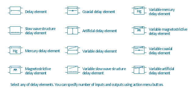
The vector stencils library "Delay elements" contains 12 symbols of delay elements for drawing electrical schematics and electronic circuit diagrams.
"An analog delay line is a network of electrical components connected in series, where each individual element creates a time difference or phase change between its input signal and its output signal. It operates on analog signals whose amplitude varies continuously. An example is a bucket-brigade device. Other types of delay line include acoustic, magnetostrictive, and surface acoustic wave devices. A series of RC networks can be cascaded to form a delay. A long transmission line can also provide a delay element. The delay time of an analog delay line may be only a few nanoseconds or several milliseconds, limited by the practical size of the physical medium used to delay the signal and the propagation speed of impulses in the medium." [Analog delay line. Wikipedia]
The symbols example "Design elements - Delay elements" was drawn using the ConceptDraw PRO diagramming and vector drawing software extended with the Electrical Engineering solution from the Engineering area of ConceptDraw Solution Park.
"Crow's Foot notation is used in Barker's Notation, SSADM and Information Engineering. Crow's Foot diagrams represent entities as boxes, and relationships as lines between the boxes. Different shapes at the ends of these lines represent the cardinality of the relationship." [Entity–relationship model. Wikipedia]
The vector stencils library ERD, crow's foot notation contains 17 symbols for creating the ER-diagrams using the ConceptDraw PRO diagramming nd vector drawing software.
The example"Design elements - ERD solution (crow's foot notation)" is included in the Entity-Relationship Diagram (ERD) solution from the Software Development area of ConceptDraw Solution Park.
 ConceptDraw Solution Park
ConceptDraw Solution Park collects graphic extensions, examples and learning materials
- Diagram Of The Types Of Lines Im Basic Design
- Types Of Lines And Their Diagrams
- Basic Flowchart Symbols and Meaning | Design elements ...
- Design elements - ERD (crow's foot notation) | Entity Relationship ...
- Basic Flowchart Symbols and Meaning | Design elements - IDEF0 ...
- Basic Flowchart Symbols and Meaning | Flowchart design ...
- Engineering Design Symbols And Their Meanings
- Design elements - ER diagram (Chen notation) | Design elements ...
- Wide area network (WAN) topology. Computer and Network ...
- Flowchart Symbols Or Design Elements
- Basic Flowchart Symbols and Meaning | Process Flowchart | Design ...
- Data Flow Diagram Symbols. DFD Library | Entity Relationship ...
- Basic Flowchart Symbols and Meaning | Process Flowchart ...
- Data Flow Diagram | Process Flowchart | Types of Flowchart ...
- Design elements - Management diagram | Computer and Networks ...
- Basic Flowchart Symbols and Meaning | Design elements - TQM ...
- Basic Flowchart Symbols and Meaning | Process Flowchart | Design ...
- Design elements - Bank UML composite structure diagram | Basic ...
- Basic Flowchart Symbols and Meaning | Flowchart design ...

.png--diagram-flowchart-example.png)