 Office Layout Plans
Office layouts and office plans are a special category of building plans and are often an obligatory requirement for precise and correct construction, design and exploitation office premises and business buildings. Designers and architects strive to make office plans and office floor plans simple and accurate, but at the same time unique, elegant, creative, and even extraordinary to easily increase the effectiveness of the work while attracting a large number of clients.
HelpDesk
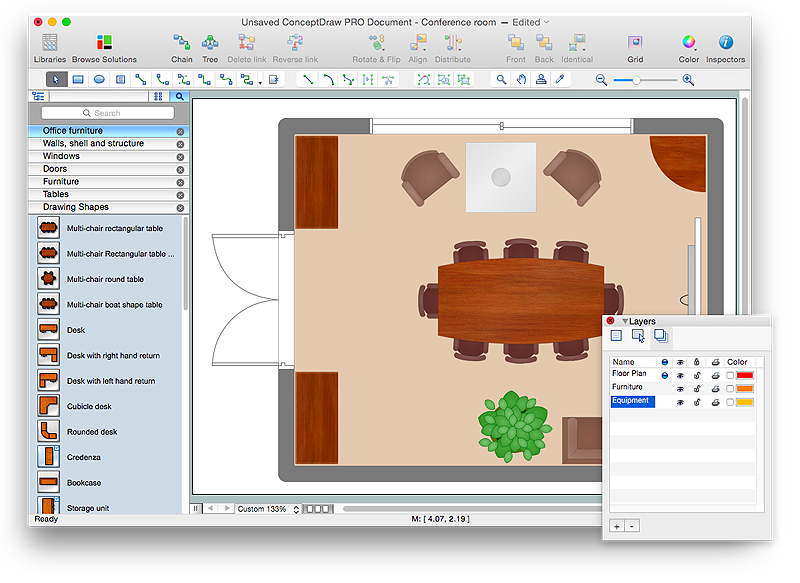
How to Draw a Floor Plan for Your Office
Designing the right office space is is an essential factor of business productivity. An office floor plan should reflect the needs of both employees and customers. ConceptDraw PRO allows you to draw the Floor Plan for your office using a special office equipment library as well as set of special objects that displays the sizes, corners, squares and other floor plan details.Design Element: Rack Diagram for Network Diagrams
ConceptDraw PRO is perfect for software designers and software developers who need to draw Rack Diagrams.
HelpDesk
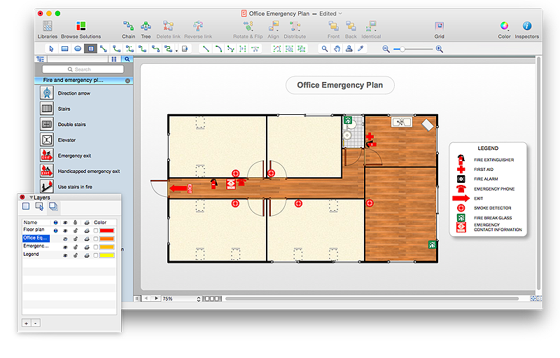
How to Draw an Emergency Plan for Your Office
Emergency Floor Plan is important to supply an office staff with a visual safety solution. Emergency Floor Plan diagram presents a set of standard symbols used to depict fire safety, emergency, and associated information. Using clear and standard symbols on fire emergency plans delivers the coherence of collective actions , helps to avoid embarrassment, and improves communications in an emergent situation. The fire emergency symbols are intended for the general emergency and fire service, as well as for building plans ,engineering drawings and insurance diagrams. They can be used during fire extinguishing and evacuation operations, as well as training. It includes vector symbols for emergency management mapping, emergency evacuation diagrams and plans. You can use ConceptDraw PRO to make the fire evacuation plans for your office simple, accurate and easy-to-read.
HelpDesk
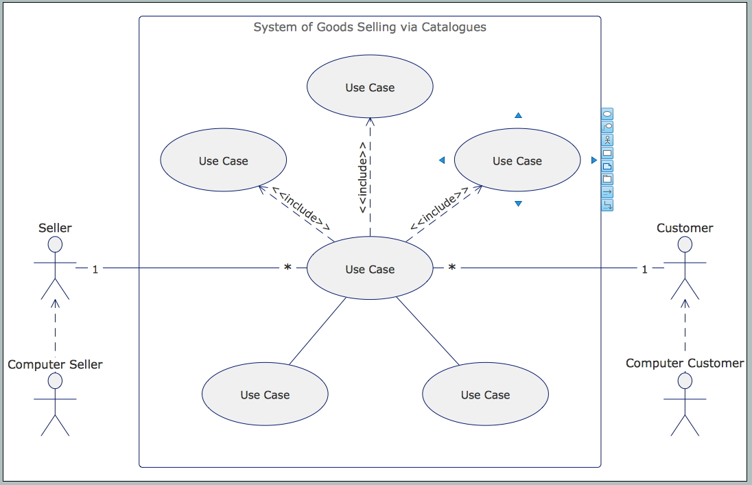
How to Create a UML Diagram Quickly
UML diagramming software with rich examples and template. ConceptDraw is ideal for software designers and software developers who need to draw UML DiagramsHelpDesk
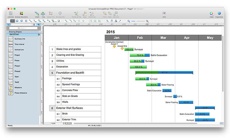
How to Draw a Gantt Chart Using ConceptDraw PRO
A Gantt chart is intended to provide a visualization of a project schedule. It is developed to help planning, coordinating, and tracking on project tasks implementation. One of the most critical resources for a project implementation is a time resources. Gantt chart - is one of the most convenient and popular way of graphical representation of a project tasks progress in conjunction with the corresponding time consumption. Gantt chart's function is to show project tasks completion in a progress, and to make a project manager sure that project tasks were completed on time. ConceptDraw Office is a clear and easy-to-use tool for project management. It is a very handy visual tool that helps make a project processing clear.
 PM Personal Time Management
This solution extends all ConceptDraw Office 2.0 products providing every project participant with a track timeframe, workspace and role in a project with the help of Microreports, calendars, and to-do lists.
 ConceptDraw Solution Park
ConceptDraw Solution Park collects graphic extensions, examples and learning materials
HelpDesk
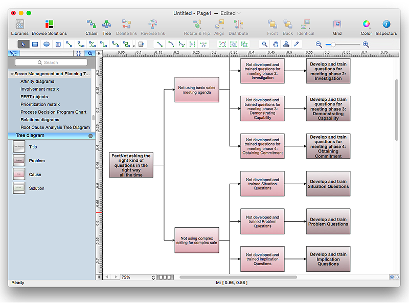
How To Create Root Cause Analysis Diagram Using ConceptDraw Office
Root Cause Analysis (RCA) is used to determine the main causes of the problem. If the certain factor is the root cause, this mean that its vanishing will help to prevent the further recurrence of the problem. Root Cause Analysis diagram is used to analyze the root causes of factors that influence the problem. It helps to identify the root causes for a factor and then propose possible corrective actions. A diagram is constructed separately for each high priority factor. The ability to create a RCA tree diagram from a mind map is supported by the ConceptDraw Seven Management and Planning Tools solution.
 Fire and Emergency Plans
This solution extends ConceptDraw software with samples, templates and design elements for drawing the Fire and Emergency Plans.
HelpDesk
How to Create a Timeline Diagram in ConceptDraw PRO
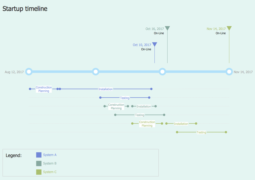
A Timeline is a chart which displays a project plan schedule in chronological order. A Timeline is used in project management to depict project milestones and visualize project phases, and show project progress. The graphic form of a timeline makes it easy to understand critical project milestones, such as the progress of a project schedule. Timelines are particularly useful for project scheduling or project management when accompanied with a Gantt chart. It captures the main of what the project will accomplish and how it will be done. making a project timeline is one of the most important skills a project manager needs have. Making comprehensive, accurate timelines allows you getting every project off in the best way. ConceptDraw PRO allows you to draw a timeline charts using special library.- Uml Office Design
- Data Flow Diagrams (DFD) | Office Layout Plans | Uml Block ...
- UML Class Diagram Example - Buildings and Rooms | Office Layout ...
- Office Layout Plans | Introduction To Component Diagram In Uml For ...
- Collaboration Area | Office Layout Plans | Spatial Infographics | Uml ...
- UML sequence diagram - Help desk | Interior Design Office Layout ...
- Office Layout Plans | PM Dashboards | IVR | Use Case Diagram For ...
- Electrical Diagram Symbols | Interior Design Office Layout Plan ...
- Plant Layout Plans | Network Layout Floor Plans | Office Layout ...
- SWOT Analysis | ATM UML Diagrams | Entity-Relationship Diagram ...
- Workflow Diagram | ATM UML Diagrams | ConceptDraw Solution ...
- Software and Database Design with ConceptDraw PRO | Office ...
- Example With Diagram Of Computer Hardware Tools
- UML Class Diagram Example - Buildings and Rooms | Room ...
- Plant Layout Plans | Building Drawing Software for Design Machines ...
- Office Layout Plans | Plant Layout Plans | Network Layout Floor ...
- Credit Card Processing System UML Diagram | Entity-Relationship ...
- UML Deployment Diagram . Design Elements | In searching of ...
- Block Diagrams | Data Flow Diagrams (DFD) | ATM UML Diagrams ...
- Enterprise Architecture Diagrams | Fishbone Diagram | UML Tool ...
.png)
