ConceptDraw Arrows10 Technology
With ConceptDraw Arrows10 Technology - You can delete a single connector, by using the Delete key. If you need to delete more than a single connector in a complex diagram that contains many relations there is a special Delete Links tool which deletes the connectors only, no other drawing objects are deleted.Bubble diagrams in Landscape Design with ConceptDraw DIAGRAM
Bubble Diagrams are the charts with a bubble presentation of data with obligatory consideration of bubble's sizes. They are analogs of Mind Maps and find their application at many fields, and even in landscape design. At this case the bubbles are applied to illustrate the arrangement of different areas of future landscape design, such as lawns, flowerbeds, playgrounds, pools, recreation areas, etc. Bubble Diagram helps to see instantly the whole project, it is easy for design and quite informative, in most cases it reflects all needed information. Often Bubble Diagram is used as a draft for the future landscape project, on the first stage of its design, and in case of approval of chosen design concept is created advanced detailed landscape plan with specification of plants and used materials. Creation of Bubble Diagrams for landscape in ConceptDraw DIAGRAM software is an easy task thanks to the Bubble Diagrams solution from "Diagrams" area. You can use the ready scanned location plan as the base or create it easy using the special ConceptDraw libraries and templates.
 Event-driven Process Chain Diagrams
Event-Driven Process Chain Diagrams solution extends ConceptDraw DIAGRAM functionality with event driven process chain templates, samples of EPC engineering and modeling the business processes, and a vector shape library for drawing the EPC diagrams and EPC flowcharts of any complexity. It is one of EPC IT solutions that assist the marketing experts, business specialists, engineers, educators and researchers in resources planning and improving the business processes using the EPC flowchart or EPC diagram. Use the EPC solutions tools to construct the chain of events and functions, to illustrate the structure of a business process control flow, to describe people and tasks for execution the business processes, to identify the inefficient businesses processes and measures required to make them efficient.
Data structure diagram with ConceptDraw DIAGRAM
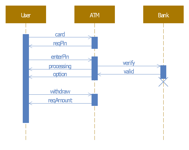
Data structure diagram (DSD) is intended for description of conceptual models of data (concepts and connections between them) in the graphic format for more obviousness. Data structure diagram includes entities description, connections between them and obligatory conditions and requirements which connect them. Create Data structure diagram with ConceptDraw DIAGRAM.This example of automated teller machine (ATM) UML sequence diagram was created on the base of figure 5 "Sequence diagram" on the webpage "Message Sequence Charts and their Ilk" from the website of the University of California Irvine (UCI) Donald Bren School of Information and Computer Sciences.
"A UML sequence diagram or SD is similar to an MSC but written with a different notation. Presumably the same semantic issues arise, but possibly not since UML semantics are not well-defined. An example is shown in Figure 5.
The timelines are dotted rather than solid, and the name of the component is inside a box at the head of each timeline. The narrow rectangles apparently show when a component is active (unsure precisely what "active" means). An X on a timeline indicates that the component ceases to exist in some sense (unsure precisely how this is meant also). In the example, the Bank timeline has an X simply as an example (presumably the Bank does continue to exist)."
[www.ics.uci.edu/ ~alspaugh/ cls/ shr/ msc.html]
This example of bank ATM sequence diagram was created using the ConceptDraw PRO diagramming and vector drawing software extended with the ATM UML Diagrams solution from the Software Development area of ConceptDraw Solution Park.
- UML Diagram | Basic Flowchart Symbols and Meaning | Normal ...
- Block Diagram | Basic Flowchart Symbols and Meaning | UML Block ...
- Basic Flowchart Symbols and Meaning | Entity Relationship ...
- UML Activity Diagram | Basic Flowchart Symbols and Meaning ...
- Design elements - ERD (crow's foot notation) | UML Notation ...
- Entity Relationship Diagram Symbols and Meaning ERD Symbols ...
- UML Diagram Types List | UML Diagrams with ConceptDraw PRO ...
- UML Class Diagram Notation
- Design elements - Bank UML composite structure diagram
- UML Diagram | Data Flow Diagram | Entity-Relationship Diagram ...
- Types of Flowcharts | Human Resource Development | UML ...
- Entity Relationship Diagram Symbols | Basic Flowchart Symbols and ...
- Process Flowchart | Basic Flowchart Symbols and Meaning | UML ...
- Basic Flowchart Symbols and Meaning | UML Use Case Diagram ...
- UML Diagrams with ConceptDraw PRO | UML Notation | UML class ...
- Basic Flowchart Symbols and Meaning | Process Flowchart | UML ...
- Basic Flowchart Symbols and Meaning | Data Flow Diagram | UML ...
- UML Diagram | UML Notation | UML class diagram - Metadata ...
- UML 2 4 Process Flow Diagram | Software Work Flow Process in ...
- UML Diagrams with ConceptDraw PRO | UML Use Case Diagram ...


