 Entity-Relationship Diagram (ERD)
Entity-Relationship Diagram (ERD) solution extends ConceptDraw DIAGRAM software with templates, samples and libraries of vector stencils from drawing the ER-diagrams by Chen's and crow’s foot notations.
 PM Docs
PM Docs solution from ConceptDraw Solution Park extends ConceptDraw MINDMAP software with the ability to create and organize the project and company documentation, to structure information that relates to your project, to link the project documentation to tasks, phases, and resources. This solution contributes for improvement the project management abilities and enhancement the productivity of project team, makes it easier to locate the pertinent documentation over the life of a project, beginning from its planning, improves the document access and minimizes search time, lets to link or embed documentation into the project topics, helps create document, design professional Mind Maps, link the correct documents to keep them organized in a project, sort the project documents and visually differentiate the document types.
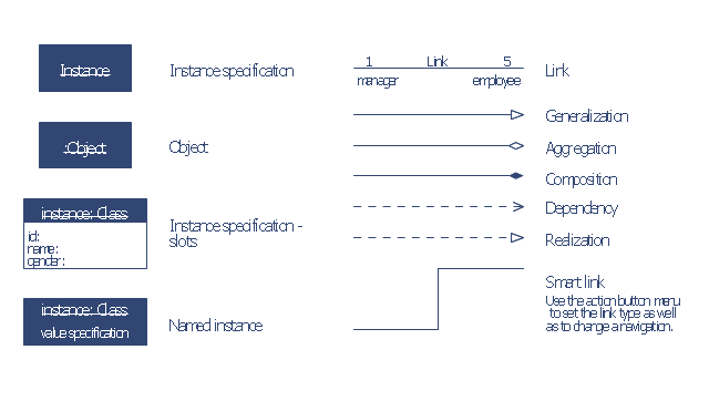
The vector stencils library "Bank UML object diagram" contains 11 shapes for drawing UML object diagrams.
Use it for object-oriented modeling of your bank information system.
"In the Unified Modeling Language (UML), an object diagram focuses on some particular set of objects and attributes, and the links between these instances. A correlated set of object diagrams provides insight into how an arbitrary view of a system is expected to evolve over time. ...
Each object and link on an object diagram is represented by an InstanceSpecification. This can show an object's classifier (e.g. an abstract or concrete class) and instance name, as well as attributes and other structural features using slots. Each slot corresponds to a single attribute or feature, and may include a value for that entity. ...
The name on an instance specification optionally shows an instance name, a ':' separator, and optionally one or more classifier names separated by commas. The contents of slots, if any, are included below the names, in a separate attribute compartment. A link is shown as a solid line, and represents an instance of an association. ...
An object instance may be called an instance specification or just an instance. A link between instances is generally referred to as a link. Other UML entities, such as an aggregation or composition symbol (a diamond) may also appear on an object diagram." [Object diagram. Wikipedia]
This example of UML object diagram symbols for the ConceptDraw PRO diagramming and vector drawing software is included in the ATM UML Diagrams solution from the Software Development area of ConceptDraw Solution Park.
Applications
ConceptDraw DIAGRAM is a multipurpose software from ConceptDraw suite intended for diagramming, business and technical drawing, and visual documenting. You can reach a lot of practical benefits from the use of ConceptDraw DIAGRAM. The list of ConceptDraw DIAGRAM applications and versatile possibilities is extremely great. Among them network and system diagramming, business diagramming, Cisco network design, network visualization, software and database design, software development, business flowcharting, data flow design, databases modeling and visualization, business processes modeling, business drawing, technical drawing, GUI prototyping, Organizational charts construction, business processes fixing, web site planning and design, Internet solutions design, information architecture design, UML modeling, ER diagrams design, home and landscape design, and a lot of other applications. ConceptDraw DIAGRAM offers the users a beneficial collaboration, compatibility with MS Visio and many other popular programs, including other products from ConceptDraw suite."A project manager is the person responsible for accomplishing the stated project objectives. Key project management responsibilities include creating clear and attainable project objectives, building the project requirements, and managing the constraints of the project management triangle, which are cost, time, scope, and quality.
A project manager is often a client representative and has to determine and implement the exact needs of the client, based on knowledge of the firm they are representing. A project manager is the bridging gap between the production team and client. So he/ she must have a fair knowledge of the industry they are in so that they are capable of understanding and discussing the problems with either party. The ability to adapt to the various internal procedures of the contracting party, and to form close links with the nominated representatives, is essential in ensuring that the key issues of cost, time, quality and above all, client satisfaction, can be realized.
The term and title 'project manager' has come to be used generically to describe anyone given responsibility to complete a project. However, it is more properly used to describe a person with full responsibility and the same level of authority required to complete a project. If a person does not have high levels of both responsibility and authority then they are better described as a project administrator, coordinator, facilitator or expeditor." [Project manager. Wikipedia]
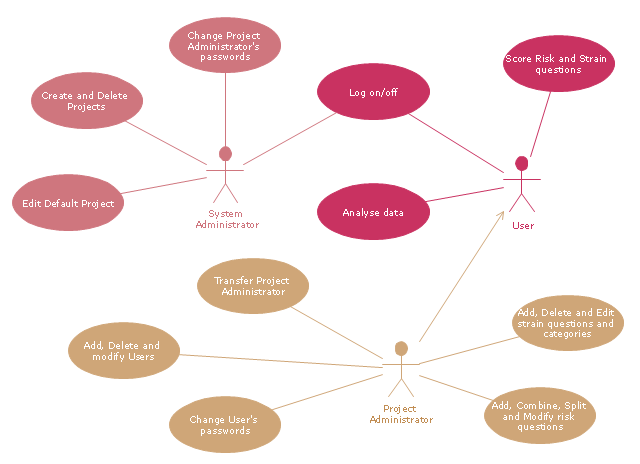
The UML use case diagram example "Project administrator" was created using the ConceptDraw PRO diagramming and vector drawing software extended with the Rapid UML solution from the Software Development area of ConceptDraw Solution Park.
- UML Notation | Notation &Symbols for ERD | Business Process ...
- Global vehicular network diagram template | UML Class Diagram ...
- Diagramming Software for Design UML Component Diagrams ...
- UML Block Diagram | Diagramming Software for Design UML ...
- UML Object Diagram. Design Elements | Business Process ...
- Diagramming Software for Design UML Activity Diagrams ...
- UML Class Diagram Example for Transport System
- Diagramming Software for Design UML Object Diagrams | UML ...
- UML Object Diagram. Design Elements | Memory Object Diagram ...
- UML activity diagram - Snap in process | Active Directory Sites and ...
- Data Flow Diagram Symbols. DFD Library | Entity Relationship ...
- Basic Flowchart Symbols and Meaning | Design elements - UML ...
- UML package diagram - Template | UML communication diagram ...
- ATM UML Diagrams | How to Create a Bank ATM Use Case ...
- UML for Bank | How to Create a Bank ATM Use Case Diagram ...
- Design elements - Events BPMN 2.0 | Events - Vector stencils library ...
- ORM Diagram | Software Diagram Examples and Templates | Gane ...
- Diagramming Software for Design UML Collaboration Diagrams ...
- Computer Networking Tools List | Basic Flowchart Symbols and ...
- Gane Sarson Diagram | Data Flow Diagram Process | Data flow ...


