UML Interaction Overview Diagram. Design Elements

This vector stencils library contains 13 symbols for drawing UML interaction overview diagrams.
Interaction

Initial Node

Decision/Merge Node

Receive Signal Node

Fork/Join Node

Final Node

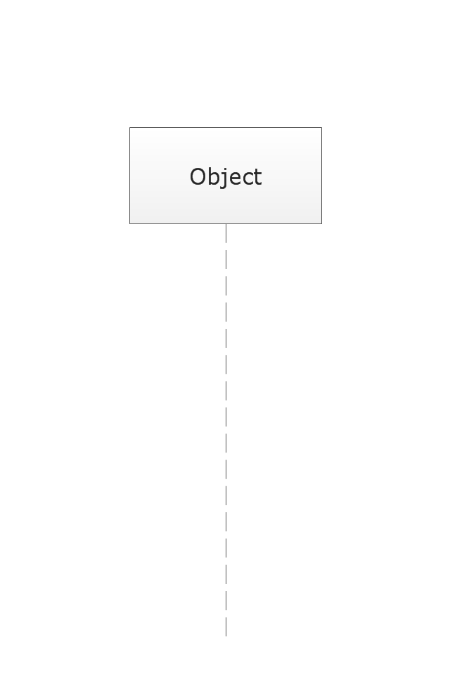
Lifeline
Message
Control Flow
Constraint

Parallel Control Flow

Smart Connector
Note
UML Activity Diagram. Design Elements


This vector stencils library contains 13 symbols for drawing UML interaction overview diagrams.
Interaction
Initial Node
Decision/Merge Node
Receive Signal Node
Fork/Join Node
Final Node
Lifeline
Message
Control Flow
Constraint
Parallel Control Flow
Smart Connector
Note
UML Notation

The vector stencils library "Bank UML interaction overview diagram" contains 11 shapes for drawing UML interaction overview diagrams.
Use it for object-oriented modeling of your bank information system.
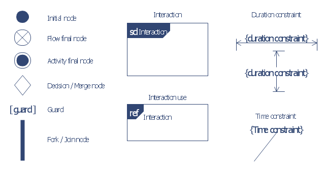
"The interaction overview diagram is similar to the activity diagram, in that both visualize a sequence of activities. The difference is that, for an interaction overview, each individual activity is pictured as a frame which can contain a nested interaction diagrams. ...
The other notation elements for interaction overview diagrams are the same as for activity diagrams. These include initial, final, decision, merge, fork and join nodes. The two new elements in the interaction overview diagrams are the "interaction occurrences" and "interaction elements"." [Interaction overview diagram. Wikipedia]
This example of UML interaction overview diagram symbols for the ConceptDraw PRO diagramming and vector drawing software is included in the ATM UML Diagrams solution from the Software Development area of ConceptDraw Solution Park.
Use it for object-oriented modeling of your bank information system.
"The interaction overview diagram is similar to the activity diagram, in that both visualize a sequence of activities. The difference is that, for an interaction overview, each individual activity is pictured as a frame which can contain a nested interaction diagrams. ...
The other notation elements for interaction overview diagrams are the same as for activity diagrams. These include initial, final, decision, merge, fork and join nodes. The two new elements in the interaction overview diagrams are the "interaction occurrences" and "interaction elements"." [Interaction overview diagram. Wikipedia]
This example of UML interaction overview diagram symbols for the ConceptDraw PRO diagramming and vector drawing software is included in the ATM UML Diagrams solution from the Software Development area of ConceptDraw Solution Park.
UML interaction overview diagram symbols
UML Flowchart Symbols

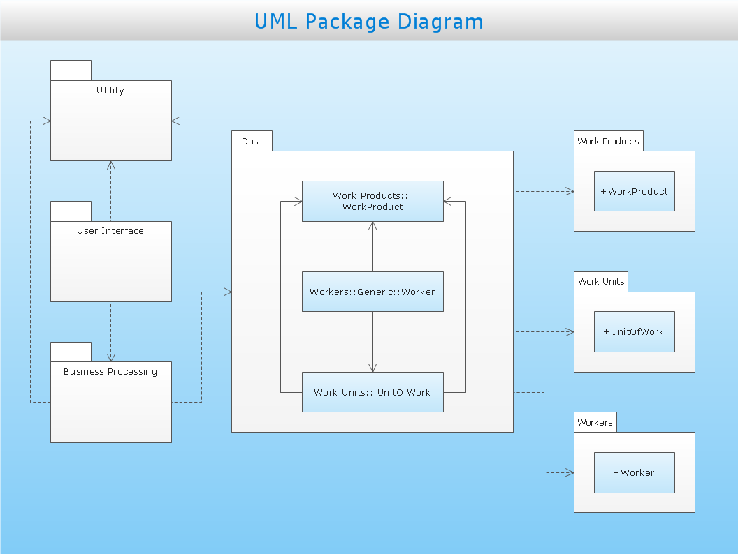
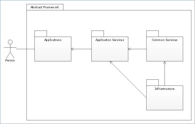
"Package diagram is UML structure diagram which shows packages and dependencies between the packages.
Model diagrams allow to show different views of a system, for example, as multi-layered (aka multi-tiered) application - multi-layered application model.
The following nodes and edges are typically drawn in a package diagram: package, packageable element, dependency, element import, package import, package merge." [uml-diagrams.org/ package-diagrams.html]
The template "UML package diagram" for the ConceptDraw PRO diagramming and vector drawing software is included in the Rapid UML solution from the Software Development area of ConceptDraw Solution Park.
www.conceptdraw.com/ solution-park/ software-uml
UML package diagram
 Rapid UML
Rapid UML solution extends ConceptDraw DIAGRAM software with templates, samples and libraries of vector stencils for quick drawing the UML diagrams using Rapid Draw technology.
- UML activity diagram - Cash withdrawal from ATM | UML activity ...
- UML interaction overview diagrams
- UML interaction overview diagrams
- UML activity diagram - Cash withdrawal from ATM | Entity ...
- Design elements - UML activity diagrams | Vector stencils library ...
- Diagramming Software for Design UML Activity Diagrams | UML ...
- Vector stencils library - Activity diagram | UML activity diagram ...
- How To Draw The Activity Node Diagram
- UML interaction overview diagram - Template | Design elements ...
- UML Activity Diagram. Design Elements | Vector stencils library ...