Entity-Relationship Diagram (ERD) with ConceptDraw DIAGRAM
Entity-Relationship Diagram (ERD) is applied for detailed description of structures and high-level (conceptual) design databases using the Chen's and Crow's Foot notations. An ERD represents a diagram constructed mainly of rectangular blocks (for entities, data) linked with relationships. The links between the blocks are used to describe relations between the entities. There are three types of relationships: one-to-one, one-to-many, and many-to-many. Use the specialized ERD software - ConceptDraw DIAGRAM to create the Entity-Relationship Diagrams (ERDs) of any degree of complexity with Chen's and Crow's Foot notations. Draw them easily applying the powerful built-in tools and libraries of predesigned ERD vector objects from Entity-Relationship Diagram (ERD) solution from the Software Development area of ConceptDraw Solution Park. You can also start with one of ready template or sample included to this solution. Designing the ERDs in ConceptDraw DIAGRAM you can easy move the objects within a diagram with saving the relationships between them.
Network Topologies
Network topology is a topological structure of computer network, which can be physical or logical. The physical topology depicts location of different computer network elements such as computers, cables and other devices. The logical topology visually displays network dataflows from one device to another. Sometimes network logical and physical topologies can be the same. ConceptDraw DIAGRAM diagramming and vector drawing software is powerful for drawing network maps and network topologies diagrams of any kinds and complexity thanks to the Computer Network Diagrams solution from the Computer and Networks area. ConceptDraw STORE proposes collection of network icons libraries and a lot of Network Topology Diagram examples, samples and templates which were created at ConceptDraw DIAGRAM software specially for Computer Network Diagrams solution. There are six basic types of the network topologies: Bus, Star, Ring, Mesh, Tree, Fully Connected. You can fast and easy design professional-looking diagram for each of them using the ConceptDraw DIAGRAM tools. There are plenty of web Visio-like diagramming software available. Web based diagrams software can be powerful, but sometimes it is essential to have desktop software. One of the most advanced diagrams tools like Visio for Mac OS is ConceptDraw DIAGRAM app.
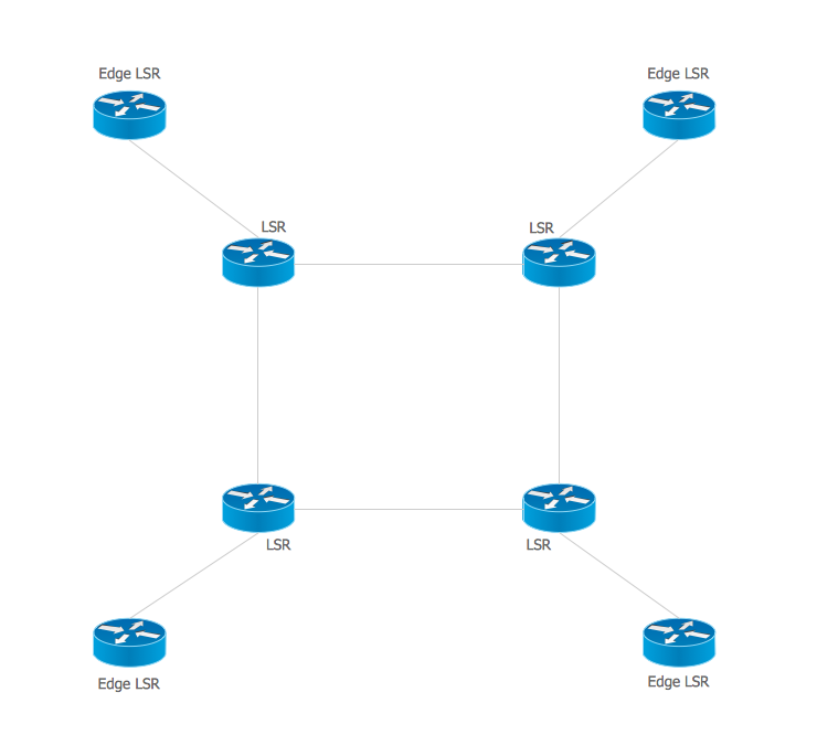
Multiprotocol Label Switching (MPLS). Computer and Network Examples
Multiprotocol Label Switching (MPLS) is a mechanism in high-performance telecommunication networks that implements the data transfer from one network node to another using the labels. ConceptDraw DIAGRAM is a powerful network diagramming and vector drawing software that provides the Computer and Networks solution with wide set of ready-to-use predesigned vector stencils and examples to help you design the MPLS Networks quick and easy.
- Recreation signs - Vector stencils library | Road signs - Vector ...
- Design elements - Astronomical symbols | Design elements ...
- Road signs - Vector stencils library | Recreation signs - Vector ...
- Road signs - Vector stencils library | Pipes 2 - Vector stencils library ...
- Unified communications diagram | Inter-vehicle communication ...
- Zodiac Star Signs Elements
- Design elements - Winter sports pictograms | Winter Sports ...
- BPR Diagram . Business Process Reengineering Example | SWOT ...
- SWOT Analysis | Block diagram - Porter's five forces model | SWOT ...
- Snowboard - Winter sports pictograms | Winter Olympics ...
- Design elements - Vehicles 2D, 3D | Industrial vehicles - Vector ...
- Example Of Company Analysis
- Design elements - Power sources | Recreation signs - Vector ...
- Snowboard - Winter sports pictograms | Design elements - Winter ...
- SWOT Analysis | Remote Projects in Corporate Strategy | Business ...
- Speed skating - Winter sports pictograms | Short track speed skating ...
- Organizational chart - University leadership | SWOT analysis for a ...
- UML Class Diagram Example for Transport System | Road Transport ...
- Cisco Optical. Cisco icons, shapes, stencils and symbols | Cisco ...
- Unified communications diagram | Telecommunication networks ...


