Physics Diagrams
ConceptDraw DIAGRAM diagramming and vector drawing software extended with Physics solution from the Science and Education area is the best for creating: physics diagrams, pictures which describe various physical facts and experiments, illustrations of various electrical, mechanical and optic processes, of any complexity quick and easy.Network Components
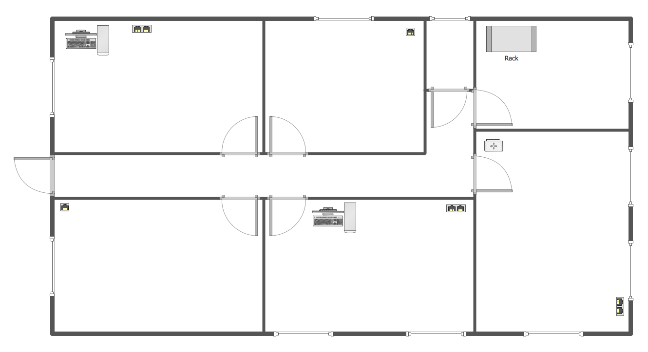
Drawing the network diagrams is a complex process which requires a lot of efforts, time and artistic abilities. ConceptDraw DIAGRAM offers the Network Layout Floor Plans Solution from the Computer and Networks Area with variety of predesigned network components for drawing network layout floor plans in minutes.Metropolitan area networks (MAN). Computer and Network Examples
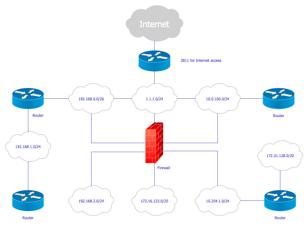
A Metropolitan Area Network (MAN) is a great computer network located on the large geographical area or region. It is a network bigger than Local Area Network (LAN), but territorially smaller than Wide Area Network (WAN), its diameter usually ranges from 5 to 50 kilometers. MAN usually includes several buildings or even the whole city (metropolis). It is based on high data rate compounds using the fiber channels and other digital data transmission channels. MAN includes a lot of communicating devices, for its construction are used multiple routers, switches and hubs. MAN can combine together several Local Area Networks or Campus Area Networks located in different buildings within a city and provides the Internet connectivity for them. Solutions included to Computer and Networks Area for ConceptDraw Solution Park are the real godsend for those who want design Computer Network Diagrams, and among others the Metropolitan Area Network Diagrams. They offer the libraries with ready-to-use vector design elements, professional-looking examples, samples and templates.
Storage area networks (SAN). Computer and Network Examples
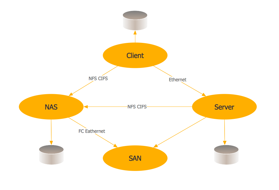
A Storage area network (SAN) is a dedicated network that provides access to data storage and operations only on the block level. SAN usually has own network of storage devices/elements and disk arrays that are connected with each other and to a remote data-sharing network. SANs are widely used for enhancing the storage devices (optical jukeboxes, disk arrays, tape libraries) that are accessible for networked servers. This example was created in ConceptDraw DIAGRAM using the Computer and Networks Area of ConceptDraw Solution Park. It shows the hybrid of Storage area network (SAN) and Network Attached Storage (NAS) technologies.
UML Deployment Diagram
UML Deployment Diagram depicts the physical deployment of artifacts on nodes (nodes are the existing hardware components, artifacts are the software components running on each node); and how the different pieces are connected. Use ConceptDraw DIAGRAM with UML deployment diagram templates, samples and stencil library from Rapid UML solution to model the physical deployment of artifacts on nodes of your software system.
Network wiring cable. Computer and Network Examples
To connect two or more network devices are used the network cables. There are more different types of the network cables: Coaxial cable, Optical fiber cable, Twisted Pair, Ethernet crossover cable, Power lines and others. They are used depending of the network topology, size, protocol. This example was created in ConceptDraw DIAGRAM using the Computer and Networks solution from the Computer and Networks area of ConceptDraw Solution Park.
Digital Communications Network. Computer and Network Examples
The digital communication is a physical transfer of the data over a point-to-point or point-to-multipoint communication channel. Channels can be copper wires, optical fibres, wireless communication channels, etc. The data are realized as electromagnetic signals (radiowave, microwave, electrical voltage, etc.). This example was created in ConceptDraw DIAGRAM using the Computer and Networks Area of ConceptDraw Solution Park and shows the Digital Communication Network diagram.
Cisco Network Design
Cisco computer network equipment developed by Cisco corporation is mainly applied in large organizations and telecommunication companies. The qualified Cisco specialists and designers often face with necessity of creation high quality charts and diagrams, and will be delighted by ConceptDraw DIAGRAM sofware. ConceptDraw DIAGRAM with Cisco Network Diagrams solution from Computers and Networks area is a powerful Cisco network design software, the best assistant for IT and telecom engineers and designers in their communication with end-users and other stakeholders. For your convenience, Cisco Network Diagrams solution provides numerous libraries of built-in Cisco symbols and design objects for network components and points, allowing fast and simply draw the Cisco Computer network diagrams, Cisco network architecture schematics, Cisco network topology designs, Network maps, Wireless network diagrams, etc. You can use the Cisco symbols to customize included predesigned samples or templates to design your new Cisco network diagrams in seconds.
Cisco Network Topology
Draw Cisco Network Topology and Cisco Computer Network Diagrams, Designs, Schematics, and Network Maps using ConceptDraw in no Time! Cisco Network Diagrams solution also provides 15 libraries of 508 Cisco symbols for network components and points, LAN and WAN, schematic and wiring drawings.Network Glossary Definition
The network glossary contains a complete list of network, computer-related and technical terms in alphabetic order, explanations and definitions for them, among them there are words well known for you and also specific, rare-used, uncommon or newly introduced terms. This specialized glossary, also known as a vocabulary, is the best in its field and covers in details the various aspects of computer network technologies. This glossary was developed by specialists using the practical experience and many useful sources to help the ConceptDraw users in their work, you can read and learn it from the screen on-line or print, it can be also used as a perfect educational guide or tutorial. ConceptDraw DIAGRAM software extended with Computer and Networks solution is easy to draw various types of Network diagrams, Network topology diagrams, Computer networking schematics, Network maps, Cisco network topology, Computer network architecture, Wireless networks, Vehicular networks, Rack diagrams, Logical, Physical, Cable networks, etc. Desktop ConceptDraw DIAGRAM Software is a good Visio for Mac Os X replacement. It gives you rich productivity and quality of the produced diagrams.
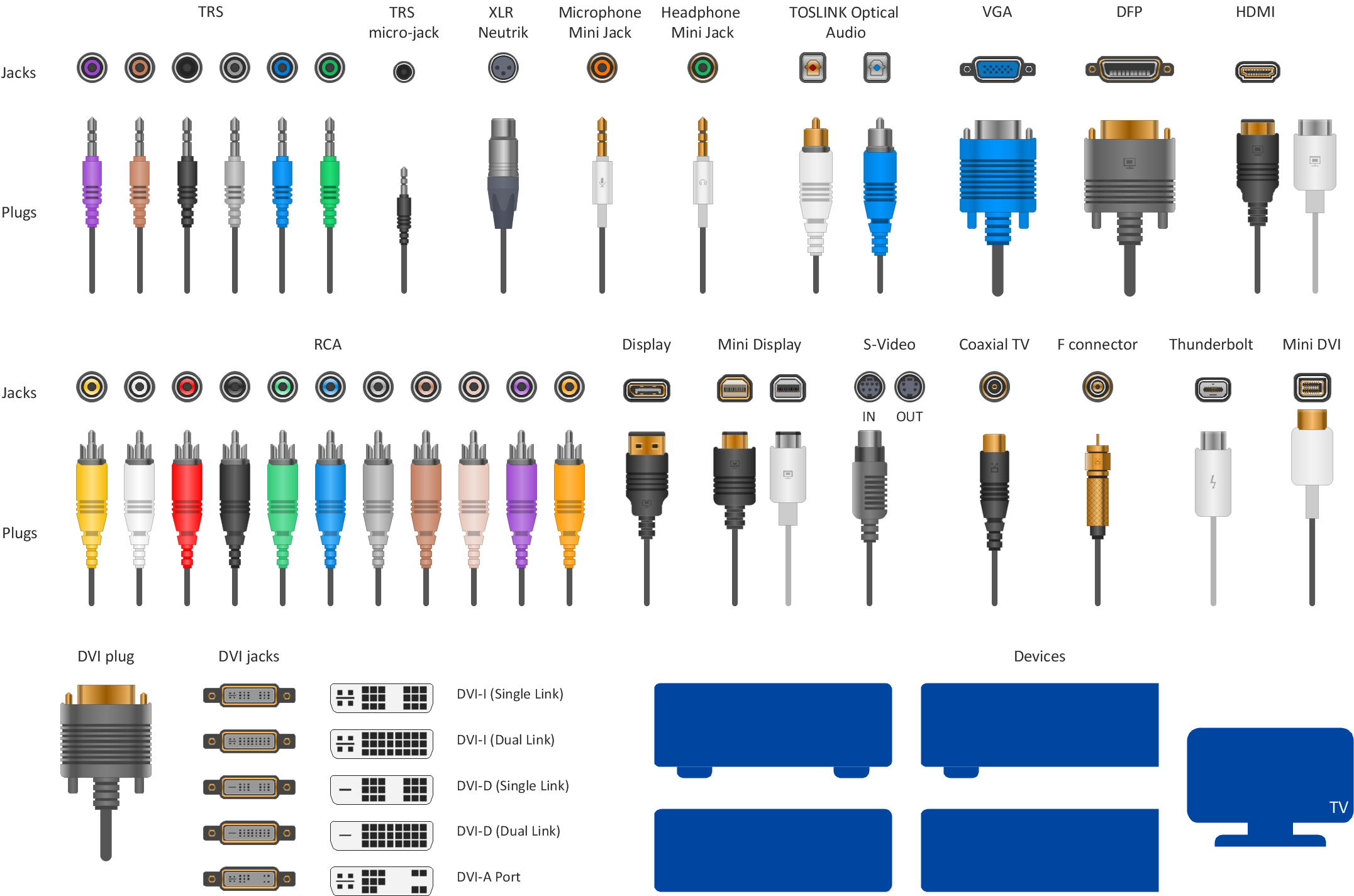
Audio Visual Connectors Types
The Audio & Video Connectors solution contains a set of pre-designed objects, libraries, templates, and samples; allowing quick and easy diagramming of various configurations of audio and video devices.Wireless network. Computer and Network Examples
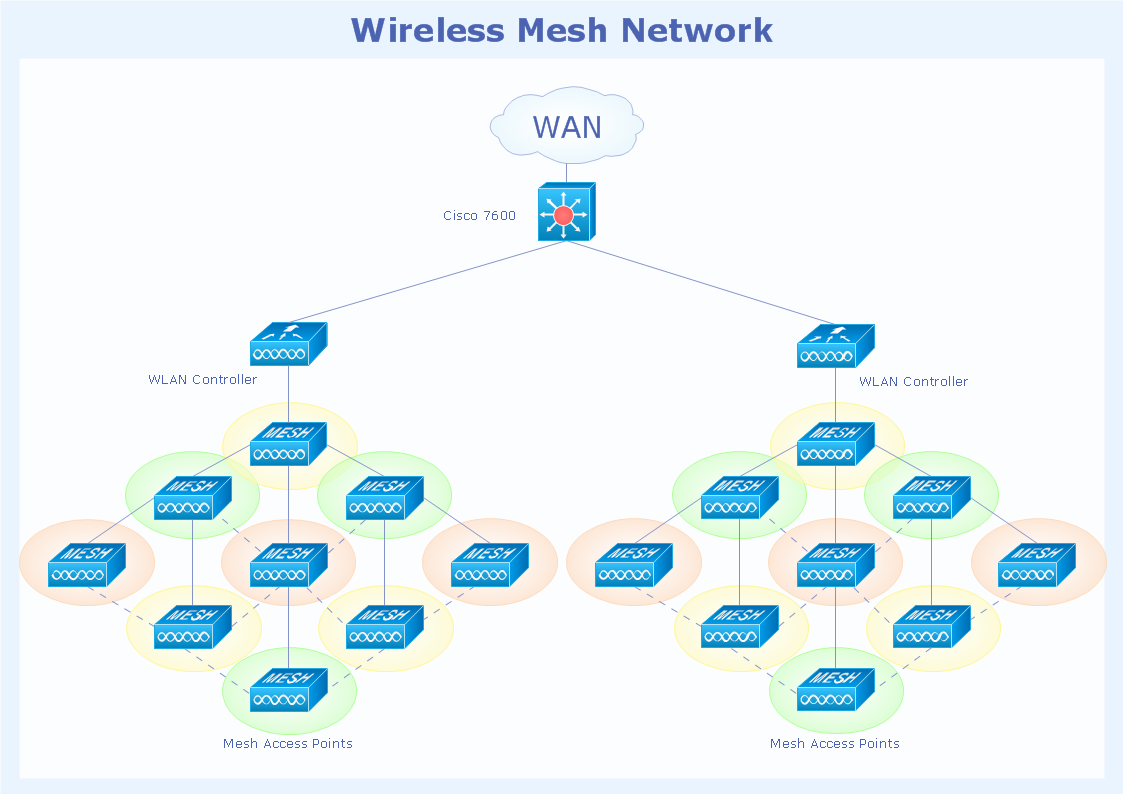
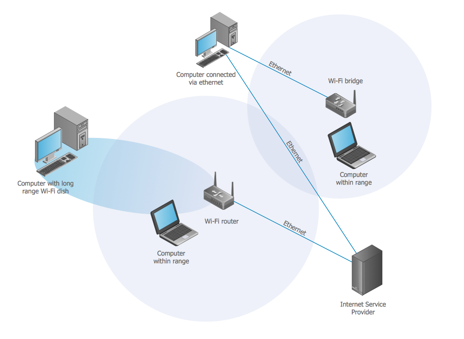
A Wireless network is a type of the computer network that uses the wireless connections for connecting network nodes for data transfer. The wireless networks are very useful, inexpensive, popular and widely used. They are easy setup and do not require the cables installation. Using the solutions of the Computer and Networks Area for ConceptDraw DIAGRAM you can design the wireless network diagrams of any complexity quick and easy.
Cable Network. Computer and Network Examples
Computer and Networks solution provides the libraries with large quantity of predesigned vector objects and the great number of templates and samples that will help design the Cable Networks in a few minutes.
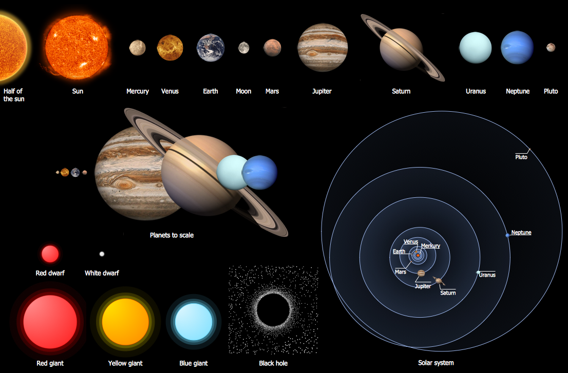
Solar System Symbols
Astronomy solution provides the Stars and Planets library with wide variety of solar system symbols. You can find here vector objects of solar system, of stars and planets of the universe. To quickly draw any astronomy illustration: create new document and simply drag the needed solar system symbols from the Stars and Planets library, arrange them and add the text. You can also use the predesigned templates and samples from the ConceptDraw STORE as the base for your own sun solar system illustrations, astronomy and astrology drawings.Audio Connectors
Audio connectors are electrical connectors designed and used for audio frequencies. ConceptDraw DIAGRAM diagramming and vector drawing software extended with Audio and Video Connectors Solution from the Industrial Engineering Area is the best for drawing various audio schematics with detailed illustration the audio connectors.- Visio Optical Symbols
- Picture Of Cisco Switch In Visio
- Optical Component Symbols
- ConceptDraw PRO Compatibility with MS Visio | Network wiring ...
- Visio Optical Fiber
- Visio Mosfet Symbol
- Point To Multipoint Icon For Visio
- Audio and video connectors - Vector stencils library | Standard ...
- Cisco Optical . Cisco icons, shapes, stencils and symbols ...
- Coaxial Cable Symbol On Visio
- Cisco Optical . Cisco icons, shapes, stencils and symbols ...
- Telecommunication Network Diagrams | Design elements ...
- Network Layout Floor Plans | Ethernet cable layout | Home ...
- Stencil Cisco Visio
- Visio Networking Stencils
- Cisco Switch Visio Icon
- Microsoft Visio Network Stencils
- Cisco Optical . Cisco icons, shapes, stencils and symbols ...
- Cisco Optical . Cisco icons, shapes, stencils and symbols | Cisco ...

