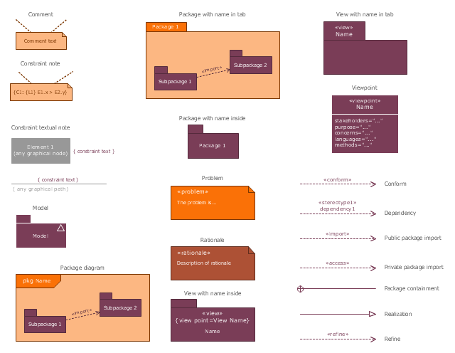
The vector stencils library "SysML diagrams" contains 19 symbols.
Use it to design your SysML diagrams using ConceptDraw PRO diagramming and vector drawing software.
"The Systems Modeling Language (SysML) is a general-purpose modeling language for systems engineering applications. It supports the specification, analysis, design, verification and validation of a broad range of systems and systems-of-systems.
SysML was originally developed by an open source specification project, and includes an open source license for distribution and use. SysML is defined as an extension of a subset of the Unified Modeling Language (UML) using UML's profile mechanism." [Systems Modeling Language. Wikipedia]
The building blocks example "Design elements - SysML diagrams" is included in the SysML solution from the Software Development area of ConceptDraw Solution Park.
HelpDesk
How to Draw a Chemical Process Flow Diagram
Process Flow Diagram widely used in modeling of processes in the chemical industry. A Chemical Process Flow diagram (PFD) is a specialized type of flowchart. With the help of Chemical Process Flow Diagram engineers can easily specify the general scheme of the processes and chemical plant equipment. Chemical Process Flow Diagram displays the real scheme of the chemical process, the relationship between the equipment and the technical characteristics of the process. Chemical Process Flow Diagram illustrates the connections between the basic equipment as well as the overall structure of pipelines and other supporting equipment. The purpose of the PFD is to build the image of the basic idea of the chemical process. ConceptDraw PRO together with its Chemical and Process Engineering solution delivers the possibility to design Chemical Process Flow diagrams. It is designed for chemical industry engineers and designers.Design Element: Rack Diagram for Network Diagrams
ConceptDraw PRO is perfect for software designers and software developers who need to draw Rack Diagrams.
- Telecommunication Network Diagrams | Design elements ...
- Building Element Name With Diagram
- Plumbing and Piping Plans | Building Drawing Design Element ...
- How To Draw Building Plans | Building Drawing Design Element ...
- Building Drawing Design Element : Piping Plan | Plumbing and ...
- Design Element : Rack Diagram for Network Diagrams | Building ...
- Design Element : Rack Diagram for Network Diagrams | Building ...
- How To Draw Building Plans | Piping and Instrumentation Diagram ...
- Building Drawing Design Element : Piping Plan | Quality Engineering ...
- Piping and Instrumentation Diagram Software | Building Drawing ...
- HVAC Plans | Block diagram - Automotive HVAC system | Design ...
- Network Building Design
- Piping and Instrumentation Diagram Software | Building Drawing ...
- Piping and Instrumentation Diagram Software | Building Drawing ...
- Chemistry | Diagram Of Building Block Of Periodic Table Of Element
- Piping and Instrumentation Diagram Software | Building Drawing ...
- How To Draw Building Plans | Design elements - Building core ...
- Piping and Instrumentation Diagram Software | Building Drawing ...
- Piping and Instrumentation Diagram Software | Building Drawing ...
- Flow Chart Symbols | Design elements - TQM diagram | Building ...


.png)