"Surveillance is the monitoring of the behavior, activities, or other changing information, usually of people for the purpose of influencing, managing, directing, or protecting them. This can include observation from a distance by means of electronic equipment (such as CCTV cameras), or interception of electronically transmitted information (such as Internet traffic or phone calls); and it can include simple, relatively no- or low-technology methods such as human intelligence agents and postal interception. ...
Surveillance is very useful to governments and law enforcement to maintain social control, recognize and monitor threats, and prevent/ investigate criminal activity. With the advent of programs such as the Total Information Awareness program and ADVISE, technologies such as high speed surveillance computers and biometrics software, and laws such as the Communications Assistance For Law Enforcement Act, governments now possess an unprecedented ability to monitor the activities of their subjects." [Surveillance. Wikipedia]
[itl.nist.gov/ iad/ 894.01/ tests/ avss/ 2009/ ]
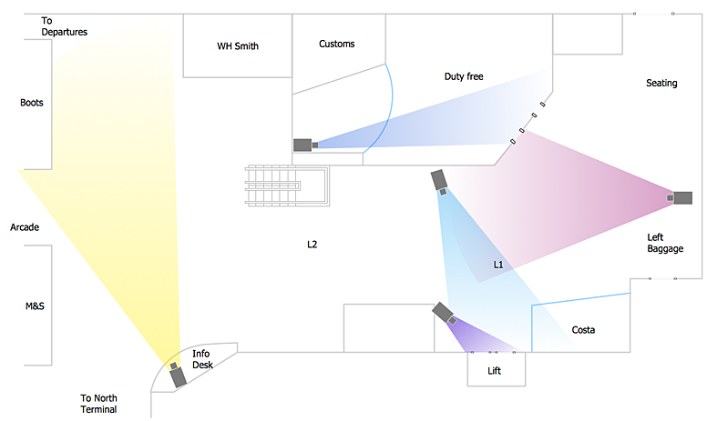
The example "Camera layout schematic" was created using the ConceptDraw PRO diagramming and vector drawing software extended with the Security and Access Plans solution from the Building Plans area of ConceptDraw Solution Park.
HelpDesk
How to Create a CCTV Diagram in ConceptDraw PRO
CCTV (Closed circuit television) diagram is used to depict a system of video monitoring. The CCTV diagram provides video cameras placement strategy. CCTV diagram should include the scheme of strategic placement of video cameras, which capture and transmit videos to either a private network of monitors for real-time viewing, or to a video recorder for later reference. CCTV is commonly used for surveillance and security purposes. Using ConceptDraw PRO with the Security and Access Plans Solution lets you create professional looking video surveillance CCTV system plans, security plans, and access schemes.
 Security and Access Plans
This solution extends ConceptDraw PRO software with physical security plan, security chart, access chart, security plans, access schemes, access plans , CCTV System Plan samples, templates and libraries of design elements for drawing the Security and Acce
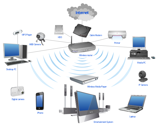
"A wireless network is any type of computer network that uses wireless data connections for connecting network nodes. Wireless networking is a method by which homes, telecommunications networks and enterprise (business) installations avoid the costly process of introducing cables into a building, or as a connection between various equipment locations. Wireless telecommunications networks are generally implemented and administered using radio communication. This implementation takes place at the physical level (layer) of the OSI model network structure. Examples of wireless networks include cell phone networks, Wi-Fi local networks and terrestrial microwave networks." [Wireless network. Wikipedia]
This wireless router network diagram example was created using the ConceptDraw PRO diagramming and vector drawing software extended with the Computer and Networks solution from the Computer and Networks area of ConceptDraw Solution Park.
This wireless router network diagram example was created using the ConceptDraw PRO diagramming and vector drawing software extended with the Computer and Networks solution from the Computer and Networks area of ConceptDraw Solution Park.
Used Solutions
How To Create Professional Diagrams
No need for any special drawing skills to create professional looking diagrams outside of your knowledge base. ConceptDraw PRO takes care of the technical side. Use templates, samples and special libraries for your needs.A simple hydraulic schematic showing apparatus for testing the strength of a hydraulic hose splice.
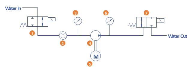
Water enters through normally closed solenoid valve (1) and passes through intake flow meter (2) to high pressure pump (4). Intake water pressure is monitored by pressure gauge (3). The hose to be tested connects between pump (4) and normally open solenoid activated drain valve (7). To test the hose, pump drive motor (5) is turned on, the solenoid of drain valve (7) is activated, closing the valve, and the pump is run to pressurize the hose. Test pressure is monitored by gauge (6). When the test is complete or the hose fails, the solenoid of drain valve (7) is deactivated, opening valve and discharging water, depressurizing the system. All components are operated electrically by a remote control circuit so that the operator may perform the test from a protected location, monitoring it with a camera and video monitor.
This hydraulic schematic example was redrawn using ConceptDraw PRO diagramming and vector drawing software from the Wikimedia Commons file: Hydraulic schematic.jpg.
[commons.wikimedia.org/ wiki/ File:Hydraulic_ schematic.jpg]
This file is licensed under the Creative Commons Attribution-Share Alike 3.0 Unported license.
[creativecommons.org/ licenses/ by-sa/ 3.0/ deed.en]
The hydraulic schematic example "Apparatus for testing the strength of a hydraulic hose splice" is included in the Mechanical Engineering solution from the Engineering area of ConceptDraw Solution Park.
- Basic CCTV System Diagram . CCTV Network Diagram Example ...
- Camera layout schematic
- How To Create CCTV Network Diagram | CCTV Network Example ...
- CCTV Surveillance System Diagram . CCTV Network Diagram ...
- Camera layout schematic | Security and Access Plans | Physical ...
- How To Create CCTV Network Diagram | Camera layout schematic ...
- How to Create a CCTV Diagram in ConceptDraw PRO | How To ...
- How To Install Cctv Camera Diagram Pdf
- How to Create a CCTV Diagram in ConceptDraw PRO | Camera ...
- Camera layout schematic | How to Create a CCTV Diagram in ...
- Symbol For Cctv Camera On Drawing
- Camera layout schematic | Physical Security Plan | Design elements ...
- How To Create CCTV Network Diagram | How To Connect Cctv ...
- Camera layout schematic
- CCTV Surveillance System Diagram . CCTV Network Diagram ...
- ConceptDraw PRO Network Diagram Tool | Daisy Chain Network ...
- CCTV Network Example | Cc Camera Block Diagram And Operation
- How To Create CCTV Network Diagram | Cctv Camera Setup Drawing
- Cctv Camera Circuit Diagram In Dvr Explanation


