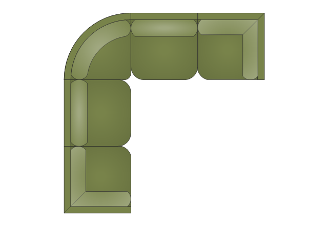
The vector stencils library "Sofas and chairs" contains 122 sofa and chair shapes.
Use it for drawing room design plans, upholstered furniture arrangement and layouts in the ConceptDraw PRO diagramming and vector drawing software extended with the Floor Plans solution from the Building Plans area of ConceptDraw Solution Park.
www.conceptdraw.com/ solution-park/ floor-plans
Use it for drawing room design plans, upholstered furniture arrangement and layouts in the ConceptDraw PRO diagramming and vector drawing software extended with the Floor Plans solution from the Building Plans area of ConceptDraw Solution Park.
www.conceptdraw.com/ solution-park/ floor-plans
The design elements library Sofas and chairs contains 122 symbols of upholstered furniture.
Use the vector stencils library Sofas and chairs for drawing room design plans, upholstered furniture arrangements, home space layout plans, interior design and furniture layouts using the ConceptDraw PRO diagramming and vector drawing software.
"A chair is a piece of furniture with a raised surface used to sit on, commonly used by one person. Chairs are most often supported by four legs and have a back; however, a chair can have three legs or could have a different shape.
A chair without a back or arm rests is a stool, or when raised up, a bar stool. A chair with arms is an armchair and with folding action and inclining footrest, a recliner. With wheels it is a wheelchair and when hung from above, a swing.
A chair for more than one person is a couch, sofa, settee, or "loveseat"; or a bench. A separate footrest for a chair is known as an ottoman, hassock or pouffe." [Chair. Wikipedia]
The shapes library Sofas and chairs is provided by the Floor Plans solution from The Building Plans area of ConceptDraw Solution Park.
The vector stencils library "Sofas and chairs" contains 122 sofa and chair shapes.
Use it for drawing room design plans, upholstered furniture arrangement and layouts in the ConceptDraw PRO diagramming and vector drawing software extended with the Floor Plans solution from the Building Plans area of ConceptDraw Solution Park.
www.conceptdraw.com/ solution-park/ floor-plans
Use it for drawing room design plans, upholstered furniture arrangement and layouts in the ConceptDraw PRO diagramming and vector drawing software extended with the Floor Plans solution from the Building Plans area of ConceptDraw Solution Park.
www.conceptdraw.com/ solution-park/ floor-plans
The vector stencils library "Office furniture" contains 36 shapes of office furnishings and work surfaces.
Use these shapes for drawing floor plans and furniture arrangements and layouts of office suites and conference rooms in the ConceptDraw PRO diagramming and vector drawing software extended with the Office Layout Plans solution from the Building Plans area of ConceptDraw Solution Park.
Use these shapes for drawing floor plans and furniture arrangements and layouts of office suites and conference rooms in the ConceptDraw PRO diagramming and vector drawing software extended with the Office Layout Plans solution from the Building Plans area of ConceptDraw Solution Park.
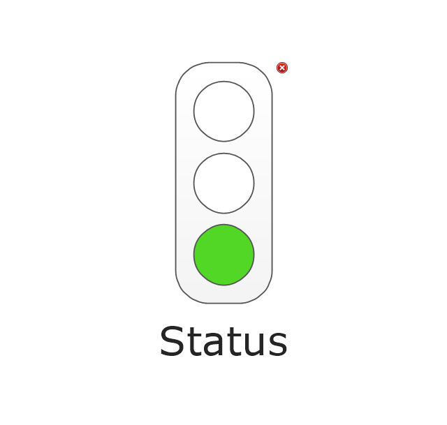
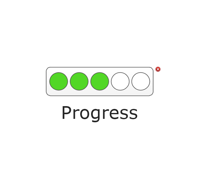
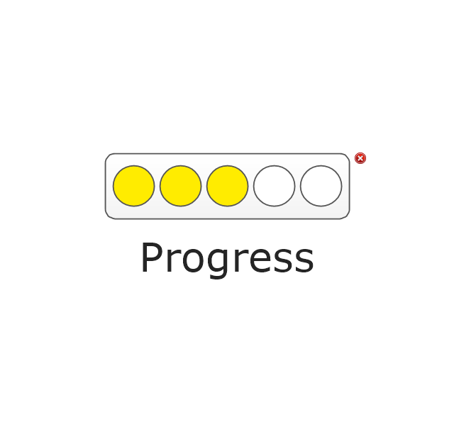
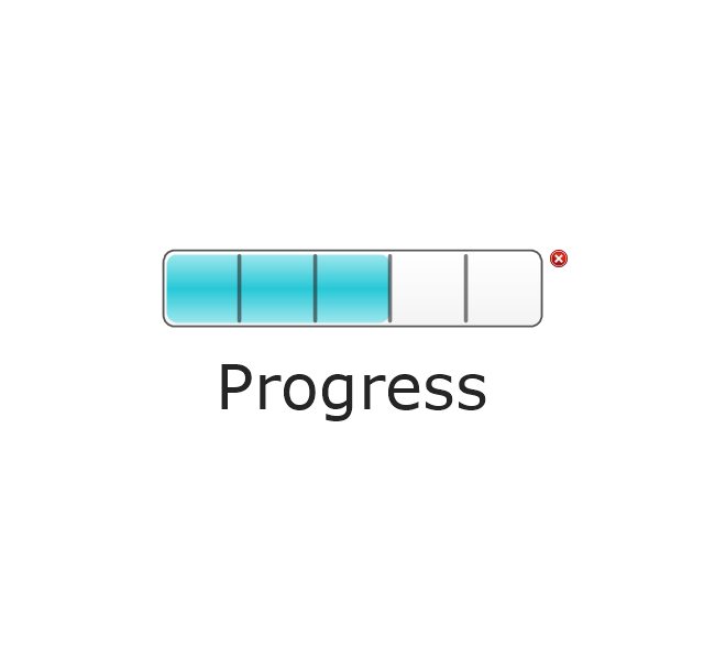
The vector stencils library "Status indicators" contains 41 visual status indicators. Each status indicator can visualize one of 2-6 information states and have a caption.
Use it to create your business performance dashboards in the ConceptDraw PRO diagramming and vector drawing software extended with the Status Dashboard solution from the area "What is a Dashboard" of ConceptDraw Solution Park.
Use it to create your business performance dashboards in the ConceptDraw PRO diagramming and vector drawing software extended with the Status Dashboard solution from the area "What is a Dashboard" of ConceptDraw Solution Park.
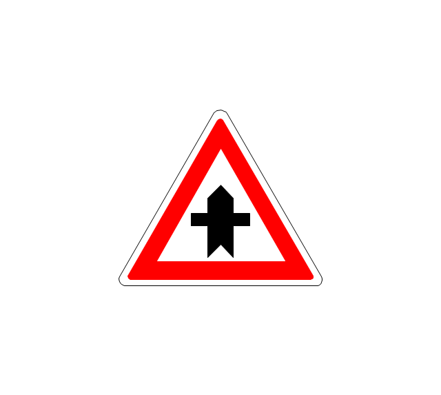
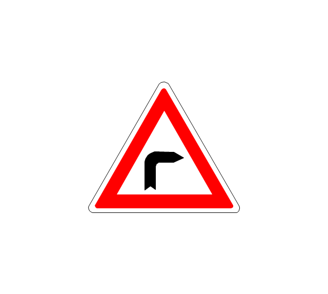
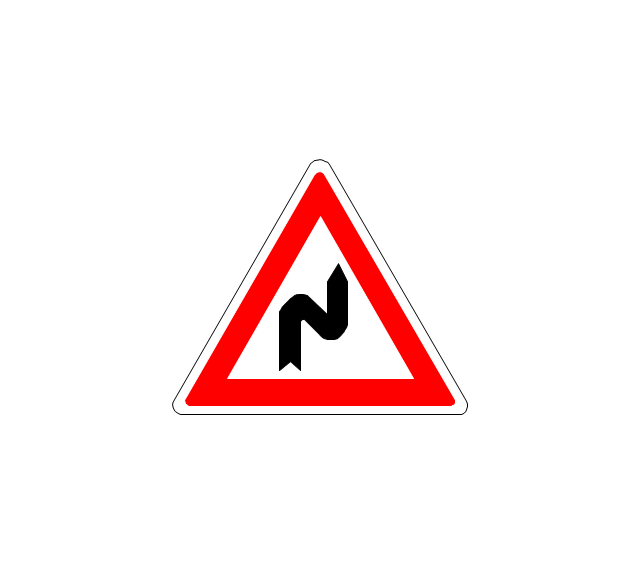
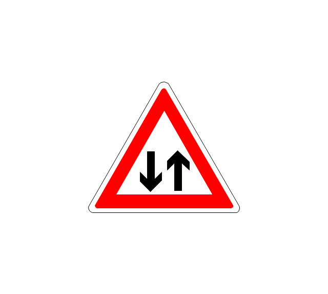
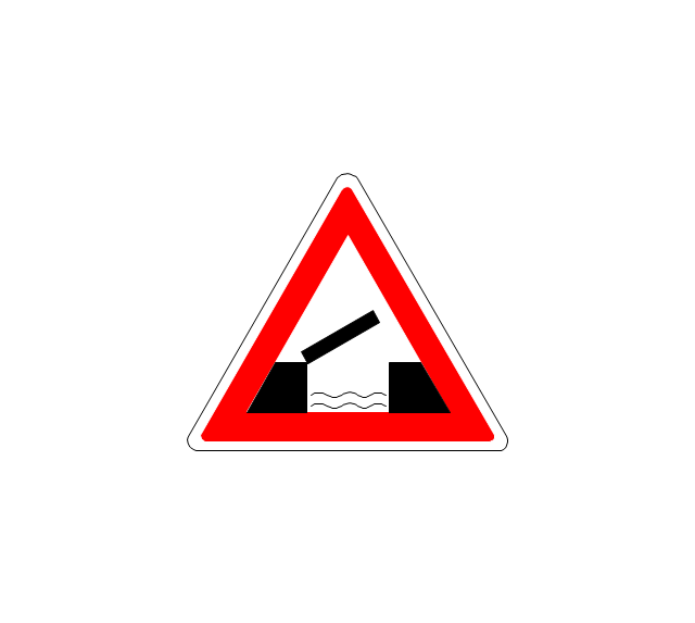
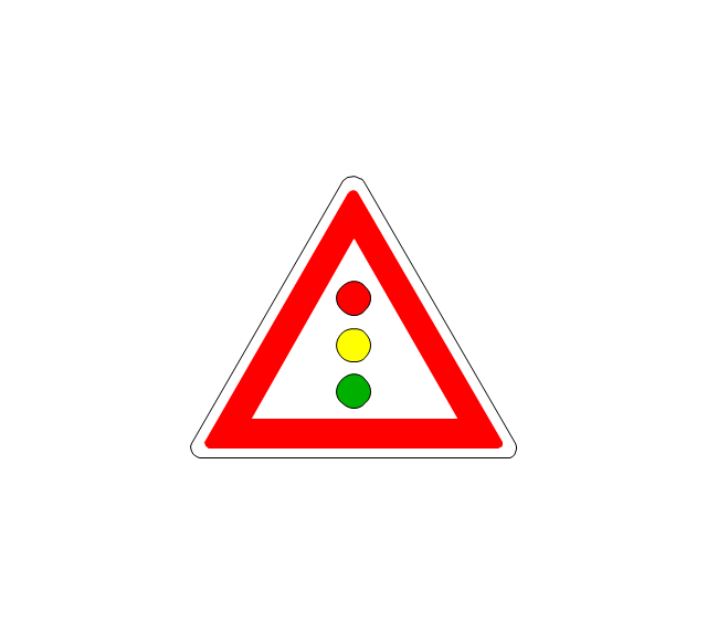
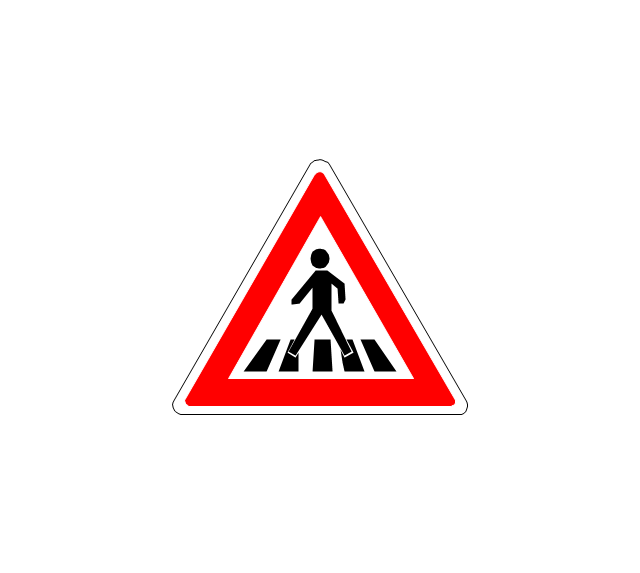
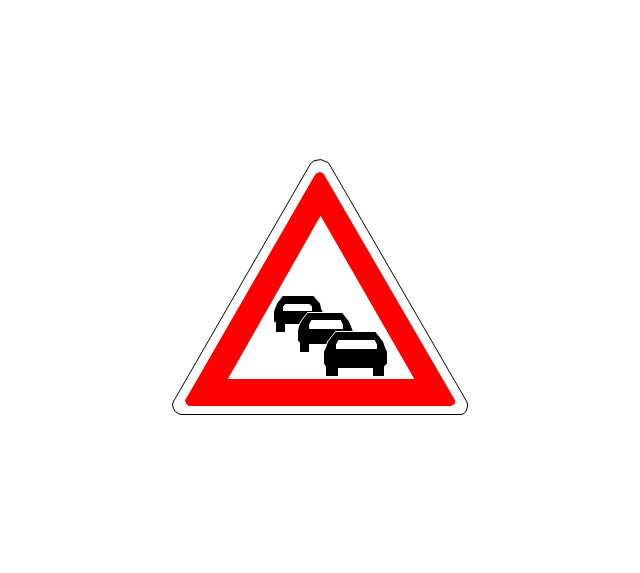
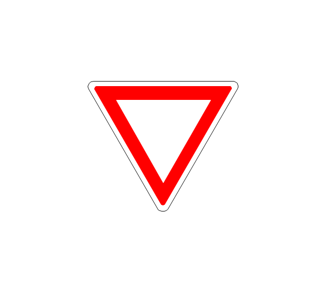
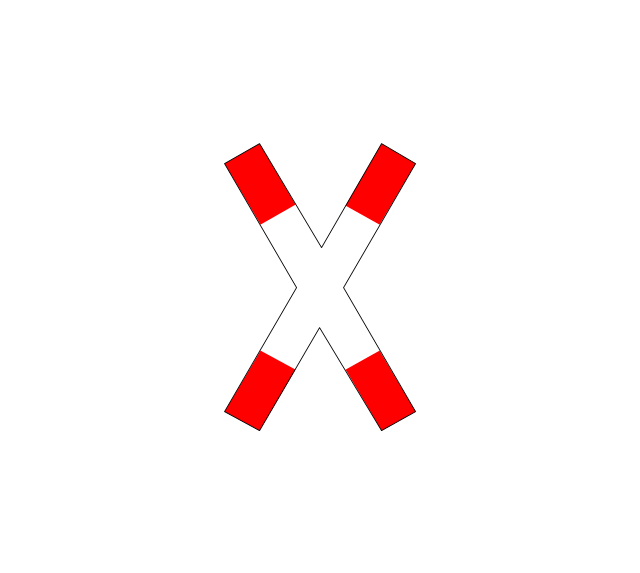
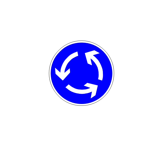
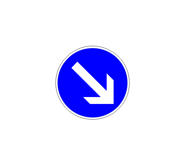
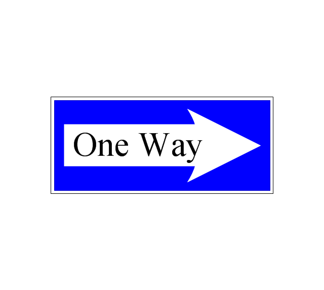
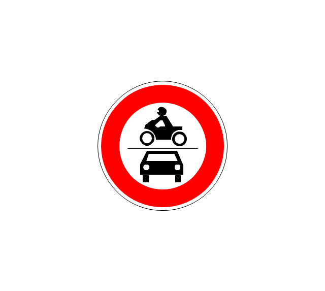
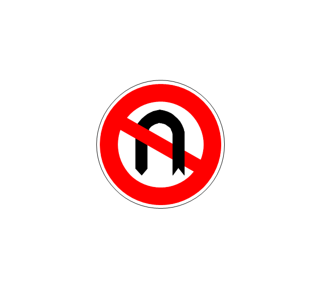
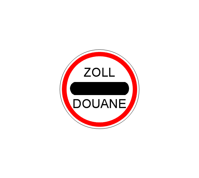
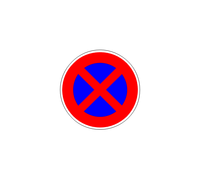
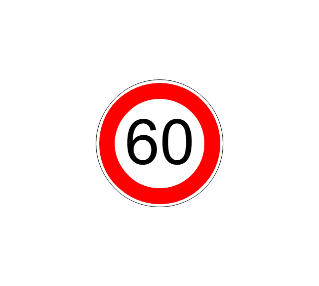
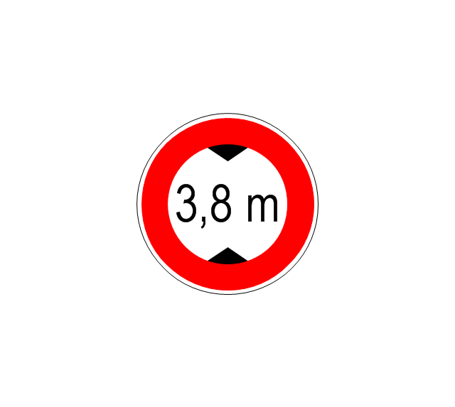
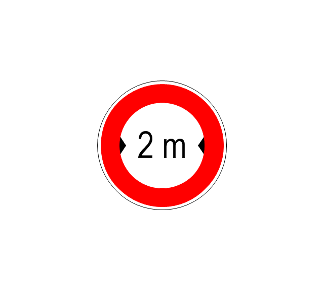
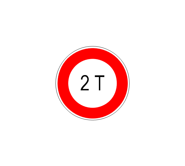
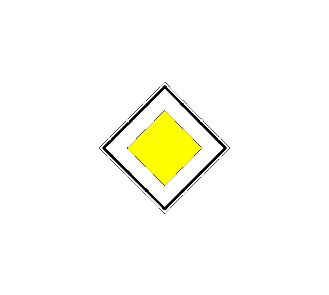
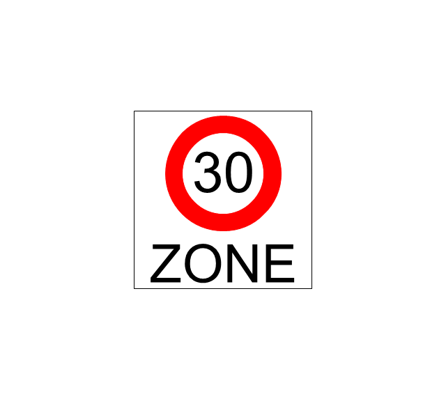
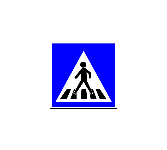
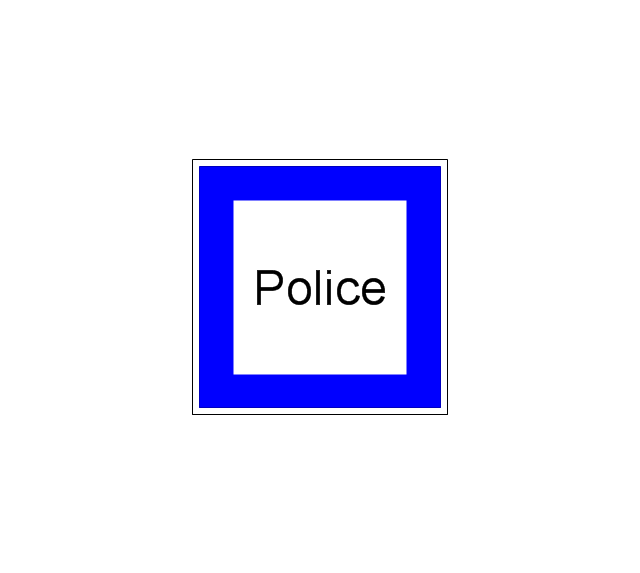
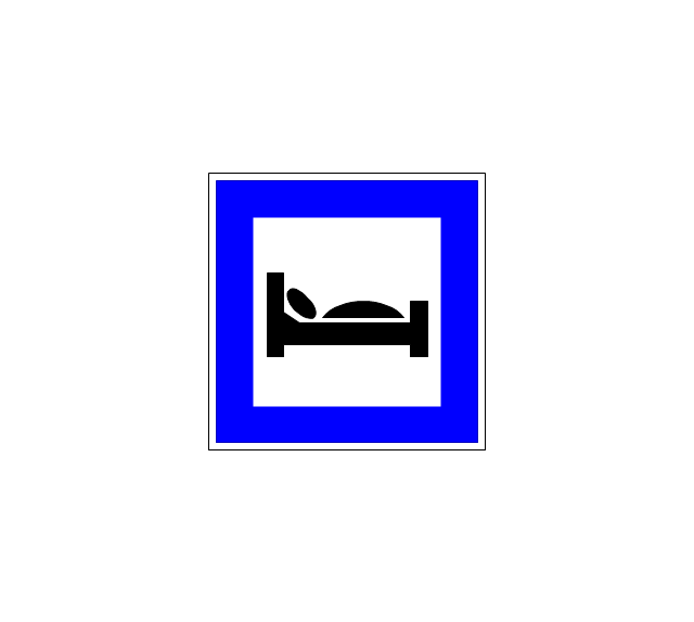
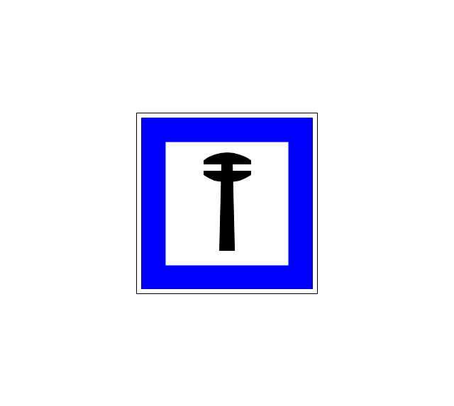
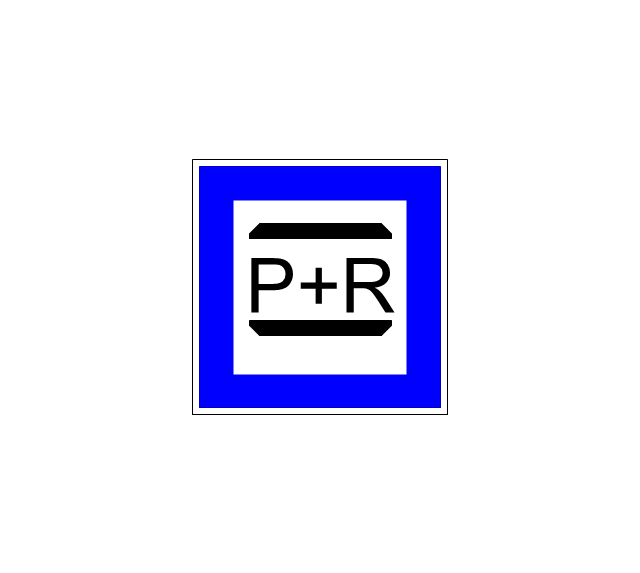
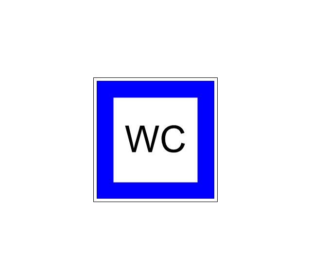
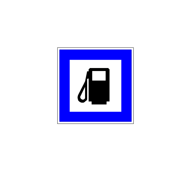
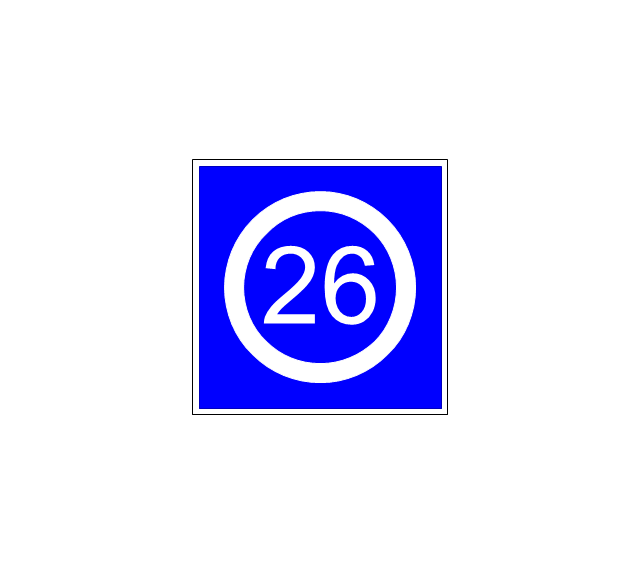
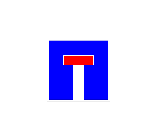
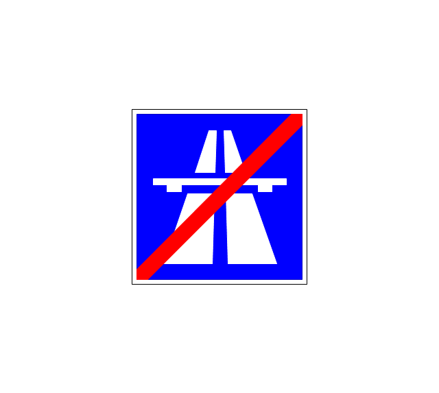
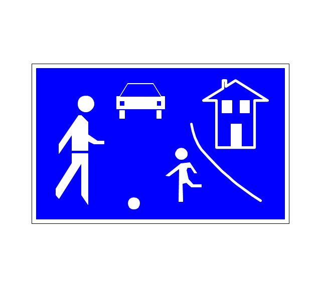
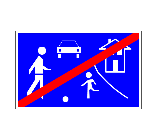
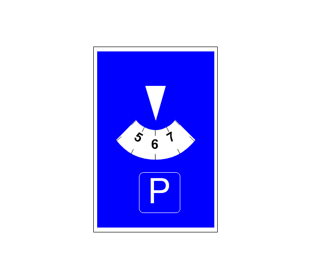
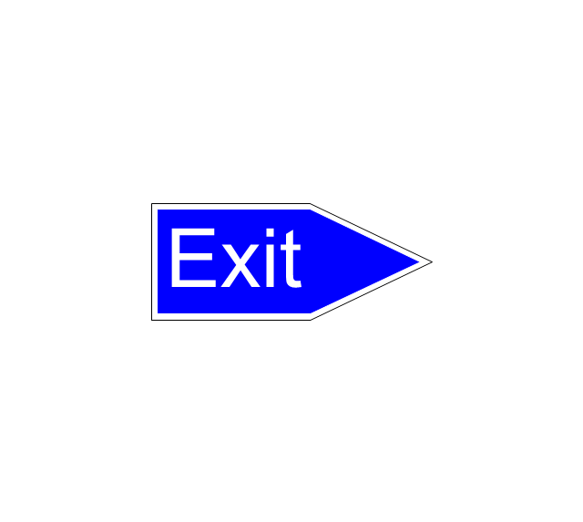
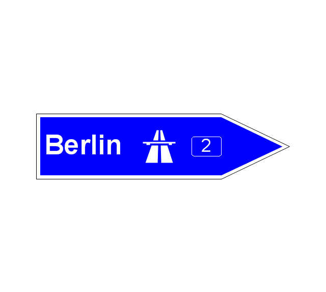
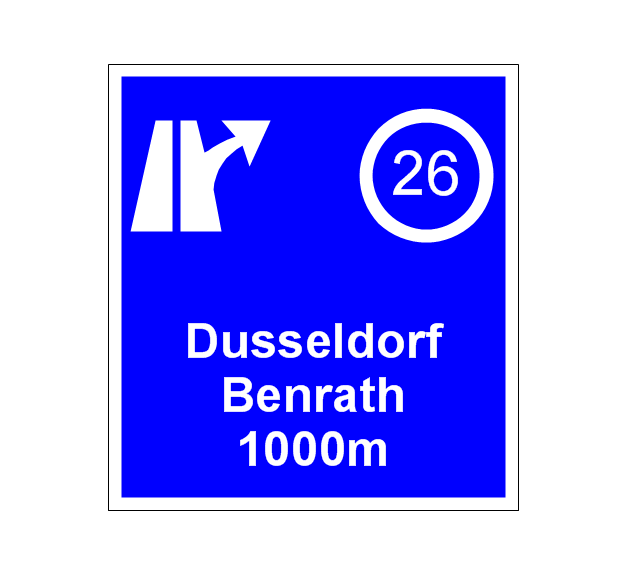
The vector stencils library "Road signs" contains 58 symbols of road signs for labeling the road and route maps, directional and transit maps, street and locator maps.
"Traffic signs or road signs are signs erected at the side of or above roads to give instructions or provide information to road users.
... many countries have adopted pictorial signs or otherwise simplified and standardized their signs to overcome language barriers, and enhance traffic safety. Such pictorial signs use symbols (often silhouettes) in place of words and are usually based on international protocols. Such signs were first developed in Europe, and have been adopted by most countries to varying degrees." [Traffic sign. Wikipedia]
The pictograms example "Road signs - Vector stencils library" was created using the ConceptDraw PRO diagramming and vector drawing software extended with the Directional Maps solution from the Maps area of ConceptDraw Solution Park.
www.conceptdraw.com/ solution-park/ maps-directional
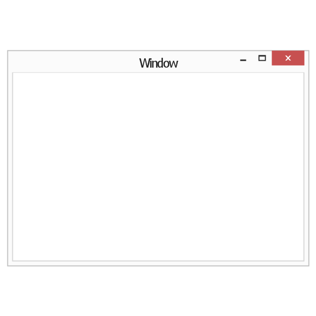
The vector stencils library "Window elements" contains 24 window elements: frames, boxes and buttons.
Use it to design graphic user interface (GUI) of your Windows 8 software application.
"A window is a graphical control element. It consists of a visual area containing some of the graphical user interface of the program it belongs to and is framed by a window decoration. It usually has a rectangular shape that can overlap with the area of other windows. It displays the output of and may allow input to one or more processes.
Windows are primarily associated with graphical displays, where they can be manipulated with a pointer by employing some kind of pointing device.
A graphical user interface (GUI) using windows as one of its main "metaphors" is called a windowing system, whose main components are the display server and the window manager." [Window (computing). Wikipedia]
The design elements example "Window elements - Vector stencils library" was created using the ConceptDraw PRO diagramming and vector drawing software extended with the Windows 8 User Interface solution from the Software Development area of ConceptDraw Solution Park.
The vector stencils library "American football positions" contains 38 american football (gridiron) players symbols.
Use it for drawing diagrams of American football positions in the ConceptDraw PRO diagramming and vector drawing software extended with the Football solution from the Sport area of ConceptDraw Solution Park.
Use it for drawing diagrams of American football positions in the ConceptDraw PRO diagramming and vector drawing software extended with the Football solution from the Sport area of ConceptDraw Solution Park.
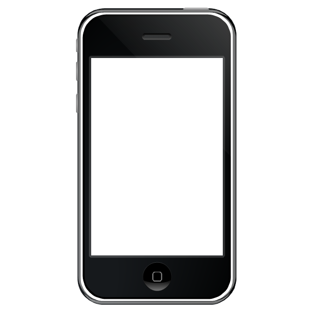
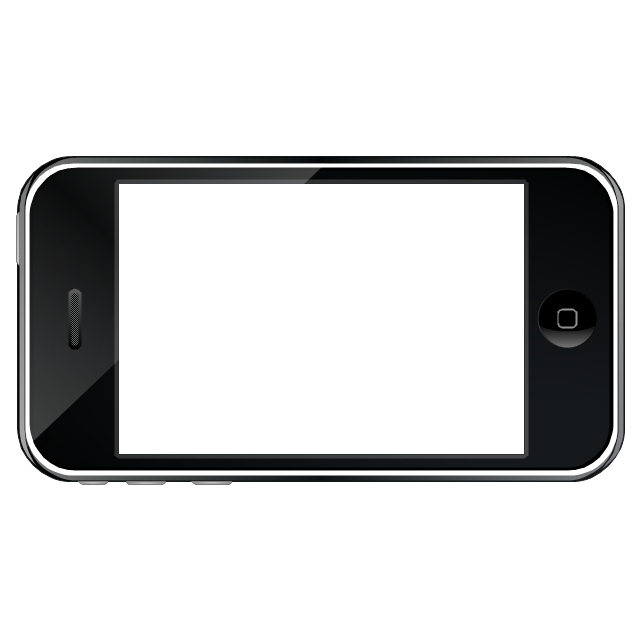
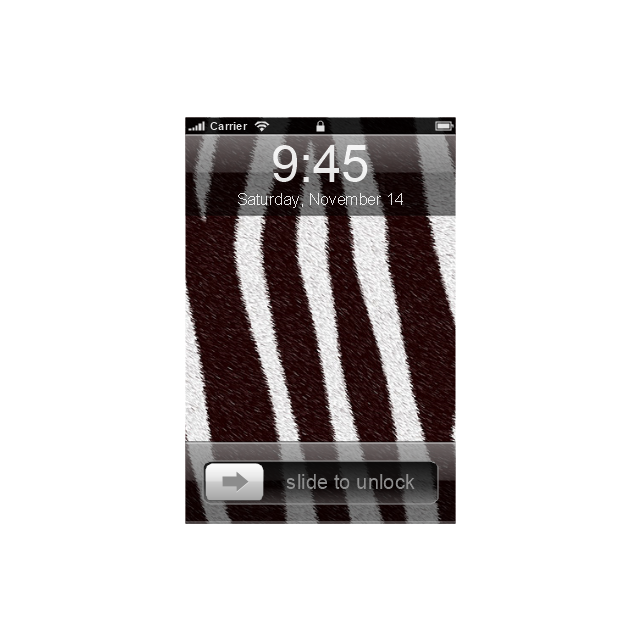
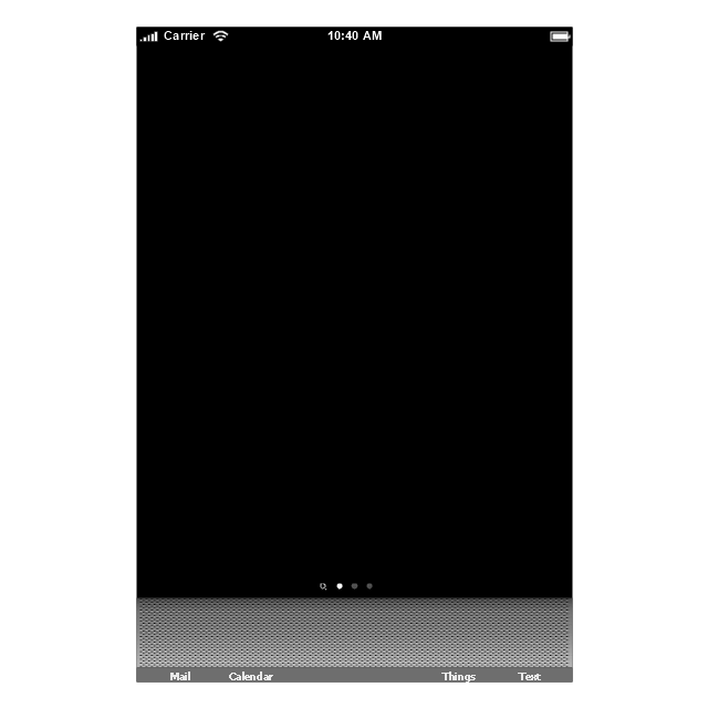
The vector stencils library "iPhone interface" contains 119 iPhone UI design elements.
Use it for development of graphic user interface (GUI) for iPhone software applications in the ConceptDraw PRO diagramming and vector drawing software extended with the Graphic User Interface solution from the Software Development area of ConceptDraw Solution Park.
Use it for development of graphic user interface (GUI) for iPhone software applications in the ConceptDraw PRO diagramming and vector drawing software extended with the Graphic User Interface solution from the Software Development area of ConceptDraw Solution Park.
"Offensive tactics in set pieces. ...
Throw-ins[edit]
How throw-ins are best handled depends on where it is:
(1) In one's own half the aim of a throw-in may be to retain possession in order to build up the next attack. The throw may or may not go toward the opponents' goal; the most unmarked player may be a full-back who is behind the ball. Such a throw followed by a quickly taken 'switch' pass can be an effective tactic. Under pressure however, the ball is often thrown up the line, toward the opponents' goal line to gain as much ground as possible.
(2) If the thrower is unmarked, a simple tactic is to take a short throw to the feet or chest of a marked player who immediately returns the ball to the thrower.
(3) In the last third of the pitch a player with a long throw can put pressure onto the defenders by throwing the ball deep into the opponents' penalty area, resulting in somewhat similar tactics to a corner kick situation, but with the added advantage of avoiding the offside trap, as an attacking player cannot be offside from a throw in. ...
Goal kicks.
A goal kick is an important 'set piece' that will occur many times in a game and yet few teams practice it. If taken quickly the kick may be taken short to a full-back who has run into a wide position. Although this may gain little ground it retains the all-important possession of the ball. A longer kick to the midfield is more common and it is vital that the midfield unit are in a position to receive it.
Corners.
A corner kick (or "corner") is a real goal scoring opportunity and it is essential to know who is the best at taking a good corner from both the left and right side of the pitch. A good corner will be aimed high across the goal and may be 'bent' towards or away from the goal. At least one of the forwards should be on or close to the goal line when the kick is taken.
Another tactic on a corner is to let the best shooter stay in the back "trash" position and have the defence worried about those up front. The player taking the corner kick makes a small pass back to the trash shooter who has time and space to take a good shot." [Association football tactics and skills. Wikipedia]
The diagram example "Association football (soccer) - The pitch: throw-ins, goal kicks, corners" was created using the ConceptDraw PRO diagramming and vector drawing software extended with the Football solution from the Sport area of ConceptDraw Solution Park.
www.conceptdraw.com/ solution-park/ sport-soccer
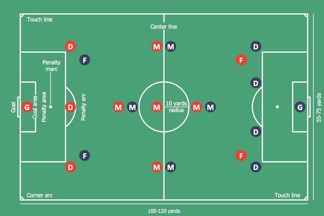
Soccer (Football) Positions
Explaining soccer positions becomes much more easier and time saving with visual drawings. ConceptDraw PRO software extended with the Soccer solution from the Sport area of ConceptDraw Solution Park is very useful tool that will help you design the soccer-related drawings of any complexity in minutes."In American football, the pro set or split backs formation is a formation that was commonly used as a "base" set by professional and amateur teams. The "pro set" formation featured a backfield that deployed two running backs aligned side-by-side instead of one in front of the other as in traditional I-formation sets. It was an outgrowth of the original, three running back T-formation, with the third back (one of the halfbacks) in the T becoming a permanent flanker, now referred to as a wide receiver. ...
A common variant of this formation removes the tight end and replaces it with a third receiver in the "slot" position. The formation is utilized to remove a defensive player from the tackle box to give the offense a 7-on-6 matchup.
There are three formations in the pro set of forms: Pro, Ace, and Tree." [Pro set. Wikipedia]
The American football positions diagram example "Pro set formation (Offense)" was created using the ConceptDraw PRO diagramming and vector drawing software extended with the Football solution from the Sport area of ConceptDraw Solution Park.
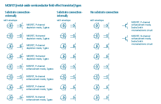
The vector stencils library "MOSFET" contains 18 symbols of MOSFET (metal–oxide–semiconductor field-effect transistor) elements for drawing electronic circuits diagrams.
"A variety of symbols are used for the MOSFET. The basic design is generally a line for the channel with the source and drain leaving it at right angles and then bending back at right angles into the same direction as the channel. Sometimes three line segments are used for enhancement mode and a solid line for depletion mode. ... Another line is drawn parallel to the channel for the gate.
The "bulk" or "body" connection, if shown, is shown connected to the back of the channel with an arrow indicating PMOS or NMOS. Arrows always point from P to N, so an NMOS (N-channel in P-well or P-substrate) has the arrow pointing in (from the bulk to the channel). If the bulk is connected to the source (as is generally the case with discrete devices) it is sometimes angled to meet up with the source leaving the transistor. If the bulk is not shown (as is often the case in IC design as they are generally common bulk) an inversion symbol is sometimes used to indicate PMOS, alternatively an arrow on the source may be used in the same way as for bipolar transistors (out for nMOS, in for pMOS). ...
For the symbols in which the bulk, or body, terminal is shown, it is here shown internally connected to the source... This is a typical configuration, but by no means the only important configuration. In general, the MOSFET is a four-terminal device, and in integrated circuits many of the MOSFETs share a body connection, not necessarily connected to the source terminals of all the transistors." [MOSFET. Wikipedia]
The symbols example "Design elements - MOSFET" was drawn using the ConceptDraw PRO diagramming and vector drawing software extended with the Electrical Engineering solution from the Engineering area of ConceptDraw Solution Park.
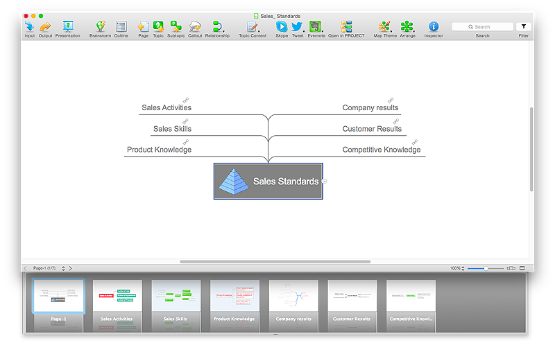
HelpDesk
How to Split a Complex Map to a Few Simple Maps
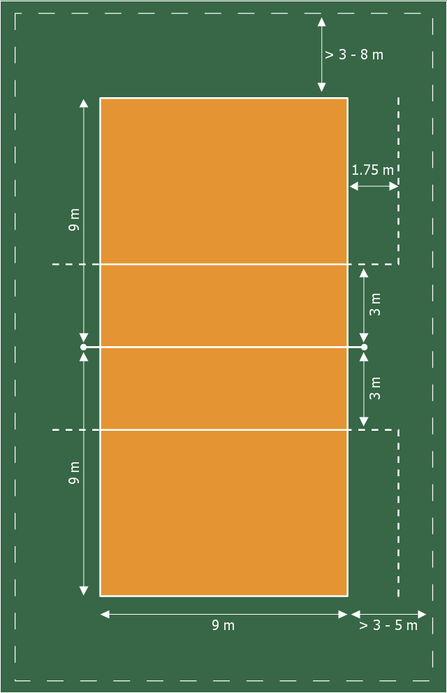
When using ConceptDraw MINDMAP, you can move each main topic of a large complex mind map to a separate page. Here is the instructions on how to create a multiple page mind map from a solid map.The sport field plan example "Volleyball court dimensions" was redesigned from the Wikipedia file: VolleyballCourt.svg. [en.wikipedia.org/ wiki/ File:VolleyballCourt.svg]
This file is licensed under the Creative Commons Attribution-Share Alike 3.0 Unported license. [creativecommons.org/ licenses/ by-sa/ 3.0/ deed.en]
"Volleyball is a team sport in which two teams of six players are separated by a net. Each team tries to score points by grounding a ball on the other team's court under organized rules. It has been a part of the official program of the Summer Olympic Games since 1964. ...
The court dimensions.
A volleyball court is 18 m (59 ft) long and 9 m (29.5 ft) wide, divided into 9 m × 9 m halves by a one-meter (40-inch) wide net. The top of the net is 2.43 m (8 ft 0 in) above the center of the court for men's competition, and 2.24 m (7 ft 4 in) for women's competition, varied for veterans and junior competitions.
The minimum height clearance for indoor volleyball courts is 7 m (23 ft), although a clearance of 8 m (26 ft) is recommended.
A line 3 m (9.84 ft) from and parallel to the net is considered the "attack line". This "3 meter" (or "10-foot") line divides the court into "back row" and "front row" areas (also back court and front court). These are in turn divided into 3 areas each: these are numbered as follows, starting from area "1", which is the position of the serving player.
After a team gains the serve (also known as siding out), its members must rotate in a clockwise direction, with the player previously in area "2" moving to area "1" and so on, with the player from area "1" moving to area "6".
The team courts are surrounded by an area called the free zone which is a minimum of 3 meters wide and which the players may enter and play within after the service of the ball. All lines denoting the boundaries of the team court and the attack zone are drawn or painted within the dimensions of the area and are therefore a part of the court or zone. If a ball comes in contact with the line, the ball is considered to be "in". An antenna is placed on each side of the net perpendicular to the sideline and is a vertical extension of the side boundary of the court. A ball passing over the net must pass completely between the antennae (or their theoretical extensions to the ceiling) without contacting them." [Volleyball. Wikipedia]
The sport field plan sample "Volleyball court dimensions" was created using the ConceptDraw PRO diagramming and vector drawing software extended with the Sport Field Plans solution from the Building Plans area of ConceptDraw Solution Park.
www.conceptdraw.com/ solution-park/ building-sport-field-plans
The vector stencils library "Office furniture" contains 36 shapes of office furnishings and work surfaces.
Use these shapes for drawing floor plans and furniture arrangements and layouts of office suites and conference rooms in the ConceptDraw PRO diagramming and vector drawing software extended with the Office Layout Plans solution from the Building Plans area of ConceptDraw Solution Park.
Use these shapes for drawing floor plans and furniture arrangements and layouts of office suites and conference rooms in the ConceptDraw PRO diagramming and vector drawing software extended with the Office Layout Plans solution from the Building Plans area of ConceptDraw Solution Park.
I Formation (Offense) Diagram
ConceptDraw PRO software extended with the Football solution delivers samples with diagrams of the most popular offenses in American Football. You can complete this set modifying any sample. All you need is to drag and drop objects to depict another offense and then save with the different name. Feel free to add text label with the offense name directly to your document.- Sofas and chairs - Vector stencils library | Round Back And Arm Sofa
- Design elements - Sofas and chairs | Sofas and chairs - Vector ...
- Sofas and chairs - Vector stencils library | Sofas and chairs - Vector ...
- Interior Design Office Layout Plan Design Element | Sofas and ...
- Sofas and chairs - Vector stencils library | Sofas and chairs - Vector ...
- Curved Back Chair 2
- Sofas and chairs - Vector stencils library | Sofas and chairs - Vector ...
- Office furniture - Vector stencils library | Sofas and chairs - Vector ...
- Design elements - Sofas and chairs | Arm Chair
- Cafe plan
- Interior Design Office Layout Plan Design Element | Interior Design ...
- Interior Design Office Layout Plan Design Element | Building ...
- Interior Design Office Layout Plan Design Element | Design ...
- Interior Design Office Layout Plan Design Element | Building ...
- Cafe Floor Plans | How To Create a Restaurant Floor Plan in ...
- How To Create Restaurant Floor Plans in Minutes | How To Create a ...
- Coffeehouse plan | Round Table Coffee Shop Chair
- 2 Circle Venn Diagram. Venn Diagram Example | Design elements ...
- Interior Design Piping Plan - Design Elements | Interior Design ...
- Café Floor Plan Example | Cafe Floor Plan Design Software | Cafe ...


















































-road-signs---vector-stencils-library.png--diagram-flowchart-example.png)
-road-signs---vector-stencils-library.png--diagram-flowchart-example.png)















-american-football-positions---vector-stencils-library.png--diagram-flowchart-example.png)
-american-football-positions---vector-stencils-library.png--diagram-flowchart-example.png)
-american-football-positions---vector-stencils-library.png--diagram-flowchart-example.png)
-american-football-positions---vector-stencils-library.png--diagram-flowchart-example.png)
-american-football-positions---vector-stencils-library.png--diagram-flowchart-example.png)
-american-football-positions---vector-stencils-library.png--diagram-flowchart-example.png)
-american-football-positions---vector-stencils-library.png--diagram-flowchart-example.png)
-american-football-positions---vector-stencils-library.png--diagram-flowchart-example.png)
-american-football-positions---vector-stencils-library.png--diagram-flowchart-example.png)
-american-football-positions---vector-stencils-library.png--diagram-flowchart-example.png)
-american-football-positions---vector-stencils-library.png--diagram-flowchart-example.png)
-american-football-positions---vector-stencils-library.png--diagram-flowchart-example.png)
-american-football-positions---vector-stencils-library.png--diagram-flowchart-example.png)
-american-football-positions---vector-stencils-library.png--diagram-flowchart-example.png)
-american-football-positions---vector-stencils-library.png--diagram-flowchart-example.png)
-american-football-positions---vector-stencils-library.png--diagram-flowchart-example.png)
-american-football-positions---vector-stencils-library.png--diagram-flowchart-example.png)
-american-football-positions---vector-stencils-library.png--diagram-flowchart-example.png)
-american-football-positions---vector-stencils-library.png--diagram-flowchart-example.png)
-american-football-positions---vector-stencils-library.png--diagram-flowchart-example.png)
-american-football-positions---vector-stencils-library.png--diagram-flowchart-example.png)
-american-football-positions---vector-stencils-library.png--diagram-flowchart-example.png)
-american-football-positions---vector-stencils-library.png--diagram-flowchart-example.png)
-american-football-positions---vector-stencils-library.png--diagram-flowchart-example.png)
-american-football-positions---vector-stencils-library.png--diagram-flowchart-example.png)
-american-football-positions---vector-stencils-library.png--diagram-flowchart-example.png)
-american-football-positions---vector-stencils-library.png--diagram-flowchart-example.png)
-american-football-positions---vector-stencils-library.png--diagram-flowchart-example.png)
-american-football-positions---vector-stencils-library.png--diagram-flowchart-example.png)
-american-football-positions---vector-stencils-library.png--diagram-flowchart-example.png)
-american-football-positions---vector-stencils-library.png--diagram-flowchart-example.png)
-american-football-positions---vector-stencils-library.png--diagram-flowchart-example.png)
-american-football-positions---vector-stencils-library.png--diagram-flowchart-example.png)
-american-football-positions---vector-stencils-library.png--diagram-flowchart-example.png)
-american-football-positions---vector-stencils-library.png--diagram-flowchart-example.png)
-american-football-positions---vector-stencils-library.png--diagram-flowchart-example.png)
-american-football-positions---vector-stencils-library.png--diagram-flowchart-example.png)
-american-football-positions---vector-stencils-library.png--diagram-flowchart-example.png)









-iphone-interface---vector-stencils-library.png--diagram-flowchart-example.png)
-iphone-interface---vector-stencils-library.png--diagram-flowchart-example.png)

















-iphone-interface---vector-stencils-library.png--diagram-flowchart-example.png)







-iphone-interface---vector-stencils-library.png--diagram-flowchart-example.png)
-iphone-interface---vector-stencils-library.png--diagram-flowchart-example.png)
-iphone-interface---vector-stencils-library.png--diagram-flowchart-example.png)
-iphone-interface---vector-stencils-library.png--diagram-flowchart-example.png)

























-tactics-diagram-association-football-(soccer)---the-pitch:-throw-ins,-goal-kicks,-corners.png--diagram-flowchart-example.png)
.png--diagram-flowchart-example.png)
-Sample.png)