Process Flowchart


"A computer network or data network is a telecommunications network that allows computers to exchange data. In computer networks, networked computing devices (network nodes) pass data to each other along data connections. The connections (network links) between nodes are established using either cable media or wireless media. The best-known computer network is the Internet.
Network devices that originate, route and terminate the data are called network nodes. Nodes can include hosts such as servers and personal computers, as well as networking hardware. Two devices are said to be networked when a device is able to exchange information with another device." [Computer network. Wikipedia]
This computer communication network diagram example was created using the ConceptDraw PRO diagramming and vector drawing software extended with the Computer and Networks solution from the Computer and Networks area of ConceptDraw Solution Park.
Network diagram

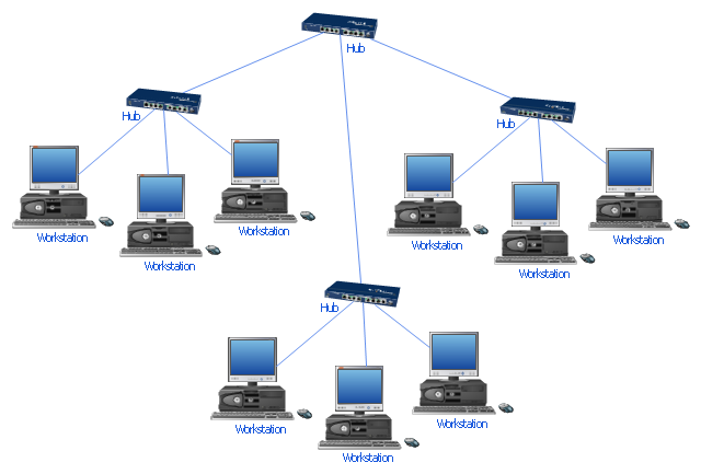
"Star networks are one of the most common computer network topologies. In its simplest form, a star network consists of one central switch, hub or computer, which act as a conduit to transmit messages. This consists of a central node, to which all other nodes are connected; this central node provides a common connection point for all nodes through a hub. In star topology, every node (computer workstation or any other peripheral) is connected to a central node called a hub or switch. The switch is the server and the peripherals are the clients. Thus, the hub and leaf nodes, and the transmission lines between them, form a graph with the topology of a star." [Star network. Wikipedia]
The computer network diagram example "10Base-T star topology" was created using the ConceptDraw PRO diagramming and vector drawing software extended with the Computer and Networks solution from the Computer and Networks area of ConceptDraw Solution Park.
The computer network diagram example "10Base-T star topology" was created using the ConceptDraw PRO diagramming and vector drawing software extended with the Computer and Networks solution from the Computer and Networks area of ConceptDraw Solution Park.
Star topology
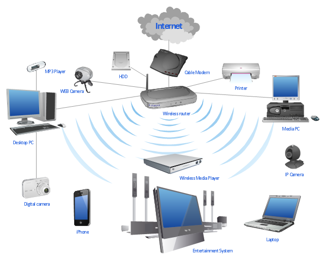
"A wireless network is any type of computer network that uses wireless data connections for connecting network nodes. Wireless networking is a method by which homes, telecommunications networks and enterprise (business) installations avoid the costly process of introducing cables into a building, or as a connection between various equipment locations. Wireless telecommunications networks are generally implemented and administered using radio communication. This implementation takes place at the physical level (layer) of the OSI model network structure. Examples of wireless networks include cell phone networks, Wi-Fi local networks and terrestrial microwave networks." [Wireless network. Wikipedia]
This wireless router network diagram example was created using the ConceptDraw PRO diagramming and vector drawing software extended with the Computer and Networks solution from the Computer and Networks area of ConceptDraw Solution Park.
This wireless router network diagram example was created using the ConceptDraw PRO diagramming and vector drawing software extended with the Computer and Networks solution from the Computer and Networks area of ConceptDraw Solution Park.
Network diagram
Used Solutions
"A bus network is a network topology in which nodes are connected in a daisy chain by a linear sequence of buses. ...
The bus is the data link in a bus network. The bus can only transmit data in one direction, and if any network segment is severed, all network transmission ceases.
A host on a bus network is called a station or workstation. In a bus network, every station receives all network traffic, and the traffic generated by each station has equal transmission priority. Each network segment is, therefore, a collision domain. In order for nodes to transmit on the same cable simultaneously, they use a media access control technology such as carrier sense multiple access (CSMA) or a bus master." [Bus network. Wikipedia]
The bus network topology diagram example was created using the ConceptDraw PRO diagramming and vector drawing software extended with the Computer and Networks solution from the Computer and Networks area of ConceptDraw Solution Park.
Bus topology

Cisco LAN. Cisco icons, shapes, stencils and symbols
")
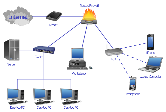
Computer network documentation is important part of industry best practices. It used by network engineers, service providers and value-added resellers (VARs) for documenting corporate and customers' networks. Network documentation is very helpful in technical maintenance, troubleshooting, upgrading and IT specialist training processes.
The basic computer network diagram example was created using the ConceptDraw PRO diagramming and vector drawing software extended with the Computer and Networks solution from the Computer and Networks area of ConceptDraw Solution Park.
The basic computer network diagram example was created using the ConceptDraw PRO diagramming and vector drawing software extended with the Computer and Networks solution from the Computer and Networks area of ConceptDraw Solution Park.
Network diagram

"Network planning and design is an iterative process, encompassing topological design, network-synthesis, and network-realization, and is aimed at ensuring that a new telecommunications network or service meets the needs of the subscriber and operator. Network planning process involves three main steps: 1) Topological design: This stage involves determining where to place the components and how to connect them. 2) Network-synthesis: This stage involves determining the size of the components used, subject to performance criteria such as the Grade of Service (GoS). 3) Network realization: This stage involves determining how to meet capacity requirements, and ensure reliability within the network." [Network planning and design. Wikipedia]
This computer network system design diagram example was created using the ConceptDraw PRO diagramming and vector drawing software extended with the Computer and Networks solution from the Computer and Networks area of ConceptDraw Solution Park.
This computer network system design diagram example was created using the ConceptDraw PRO diagramming and vector drawing software extended with the Computer and Networks solution from the Computer and Networks area of ConceptDraw Solution Park.
Network system design
Star Network Topology


Network Topologies

Mesh Network. Computer and Network Examples


Wireless Network WLAN

Control and Information Architecture Diagrams (CIAD) with ConceptDraw PRO

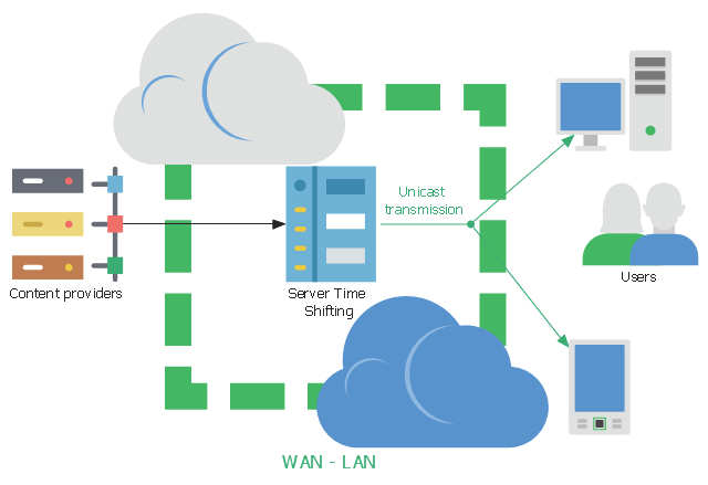
This network diagram sample shows the video on demand (VoD) architecture in a network video recorder (NVR) enviroment. It was designed on the base of Wikimedia Commons file: BaixdemandaArchitecture.png.
[commons.wikimedia.org/ wiki/ File:BaixdemandaArchitecture.png]
This file is licensed under the Creative Commons Attribution-Share Alike 3.0 Unported license. [creativecommons.org/ licenses/ by-sa/ 3.0/ deed.en]
"Video on demand (display) (VOD) are systems which allow users to select and watch/ listen to video or audio content when they choose to, rather than having to watch at a specific broadcast time. IPTV technology is often used to bring video on demand to televisions and personal computers." [Video on demand. Wikipedia]
The network diagram example "VoD architecture in a NVR enviroment" was created using the ConceptDraw PRO diagramming and vector drawing software extended with the Computers and
Communications solution from the Illustration area of ConceptDraw Solution Park.
Network diagram
Network Topology Mapper

- Diagrams For Workstation
- Server Host Workstations Diagram
- Workstation Diagram
- Network Diagram Including Workstation Switch Server Router
- Network Diagram Workstation
- Communication network diagram | Telecommunication Network ...
- Network Glossary Definition | Bus network topology diagram ...
- A Network Diagram Workstation Switch Server Router Firewall
- Wireless router network diagram | What Is a Wireless Network ...
- Basic computer network diagram | Physical LAN and WAN diagram ...
- Physical LAN and WAN diagram - Template
- Fully Connected Network Topology Diagram | Local area network ...
- Wireless Networking Model Diagram
- Diagram Of Workstation
- Network Diagram Switch Router Workstation Wap
- Three Workstation Wan Diagram
- Workstation Server Diagram In Ds
- Computer network system design diagram | Design elements ...
- Bus Topology Diagram
- Star Network Topology | Network Topologies | Fully Connected ...