Entity Relationship Diagram Software Engineering . Professional
In order to model some data, illustrate the logical structure and system design of databases, the Entity Relationship Diagram (ERD or ER Diagram as well as E-R Diagram) was introduced by Peter Chen as a modeling technique for software development. Using three main elements which are attributes, entities and relationships make possible to create so called ERD and to do it with help of ConceptDraw DIAGRAM software is simpler than ever now. As once you download ConceptDraw STORE, you will find the samples of ERDs which you can use for making your own diagram in short terms using all the elements necessary for this purpose. Immensely popular in software engineering this method for modeling database is common for IT engineers use as well as any other IT specialists once they want to succeed in their job. So why not to try our application just now to make sure you keep up with the times and use all necessary tools for achieving your goals?
 Chemical and Process Engineering Solution. ConceptDraw.com
This chemical engineering solution extends ConceptDraw DIAGRAM .9.5 (or later
) with process flow diagram symbols, samples, process diagrams templates
 Mechanical Engineering Solution. ConceptDraw.com
This solution extends ConceptDraw DIAGRAM .9 mechanical drawing software (
or It uses, apart from engineering itself, also physics and materials science
Electrical Symbols, Electrical Diagram Symbols
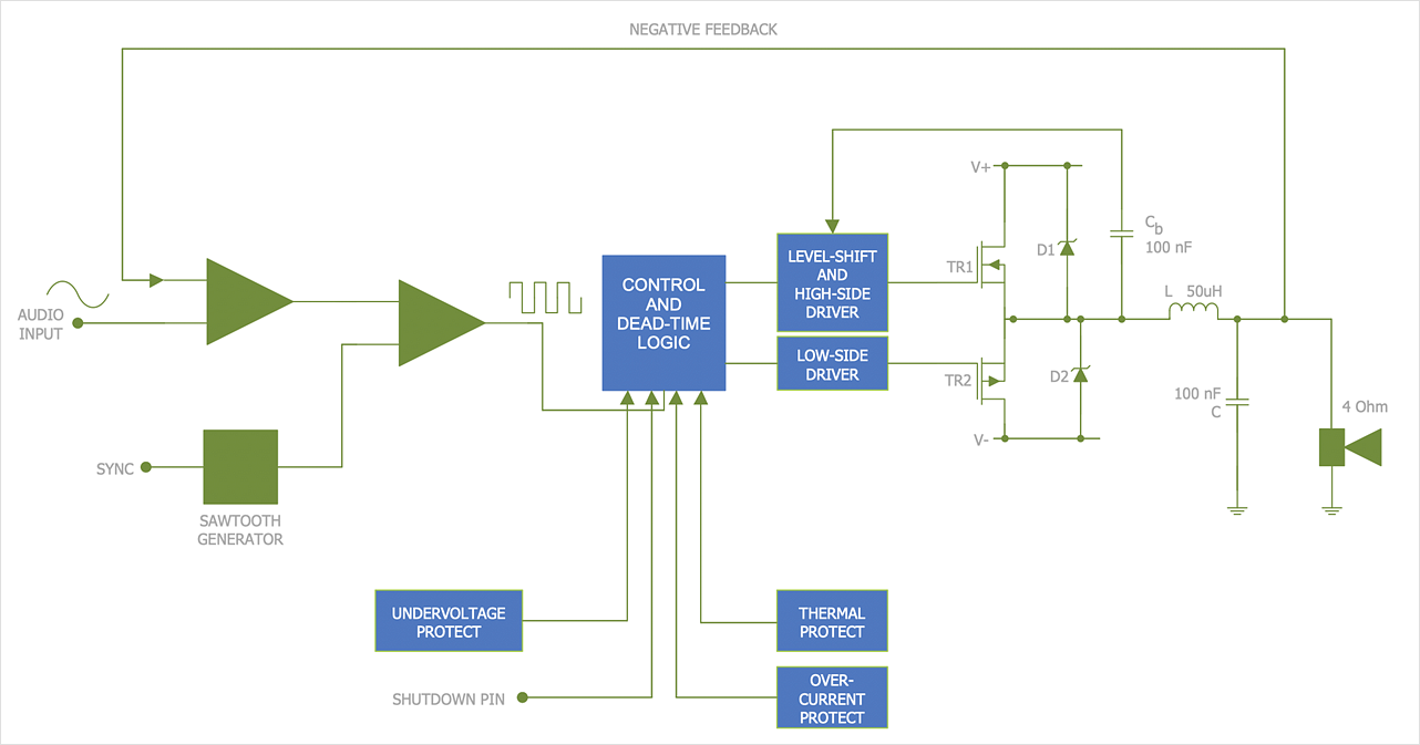
Once you have to draw some electrical diagram, then you can use ConceptDraw DIAGRAM for making it within a couple of minutes having numerous libraries of stencil elements, such as VHF, UHF, SHF, Transmission Paths, Transistors, Transformers and Windings, Thermo, Terminals and Connectors with 43 design elements, Switches and Relays with 58 symbols, Stations with 110 symbols, Semiconductors with 22 elements, Semiconductor Diodes with 24, Rotating Equipment with 55, Resistors with 14 design elements, Qualifying with 56, Power Sources with 9 symbols as well as Maintenance one which were previously made by the specialists with help of our designers so our clients have all kinds of needed stencils to create any kind of diagram, plan, chart or flowchart, or scheme. Downloading our application is the first step to make sure the final diagram will look very smart and professional.HelpDesk
Creating a Create a Mechanical Diagram . ConceptDraw HelpDesk
Making Mechanical Engineering diagram involves many different elements that can be managed using ConceptDraw DIAGRAM The ability to design elements
 Electrical Engineering Solution. ConceptDraw.com
This solution extends ConceptDraw DIAGRAM .9.5 (or later) with electrical
engineering samples, electrical schematic symbols, electrical diagram symbols,
HelpDesk
Creating Electrical Diagrams . ConceptDraw HelpDesk
The ability to create electrical diagrams and schematic using ConceptDraw DIAGRAM is delivered by the Electrical Engineering solution. The solution suppliedQuality Engineering Diagrams . Value Stream Mapping Software
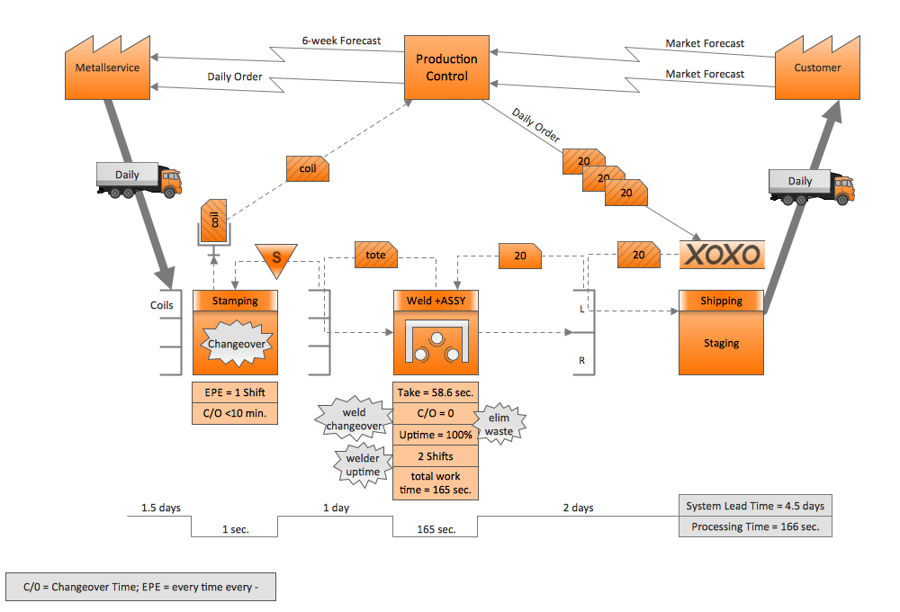
Quality Engineering Diagrams - Value stream mapping (VSM) sampleMechanical Drawing Symbols
Working as a mechanic being responsible for making the appropriate drawings, including technical ones, working with ventilating, heating or air conditioning, you may find it exhausting creating all of schemes by hand using the ruler, for example. In this case we can recommend to download ConceptDraw DIAGRAM which is professional software that can make your life simpler and help you to achieve your goals at work in your business. 8 libraries are available with 602 commonly used mechanical drawing symbols in Mechanical Engineering Solution, including libraries called Bearings with 59 elements of roller and ball bearings, shafts, gears, hooks, springs, spindles and keys; Dimensioning and Tolerancing with 45 elements; Fluid Power Equipment containing 113 elements of motors, pumps, air compressors, meters, cylinders, actuators and gauges; Fluid Power Valves containing 93 elements of pneumatic and hydraulic valves (directional control valves, flow control valves, pressure control valves) and electrohydraulic and electropneumatic valves; as well as many other sophisticated symbols and templates for your use.Technical Drawing Software
Being a technologist, engineer, designer, architect or technician can put lots of pressure on you, especially when you have to create lots of drawings within your work hours, such as technical schemes and plans. Making diagrams you need proper professional software with available samples to be able to use them as the drafts in terms of creating your own schemes. In case you have enough symbols and design elements, as well as templates and examples for drawing everything you need in respect of completing your work on time, you might like using the very special software ConceptDraw DIAGRAM with extension as it is one of the best and sophisticated tools for engineers and technicians. There are 8 libraries of 602 design elements in Mechanical Engineering Solution, 26 libraries of 926 design elements in Electrical Engineering Solution and 8 libraries of 468 design elements in Chemical and Process Engineering Solution which should be more than enough for technical drawing.
 Jackson Structured Programming (JSP) Diagram Solution
The powerful abilities of this solution make the ConceptDraw DIAGRAM ideal
assistant structural programmers, computer engineers , applications
constructors,
- Mechanical Drawing Symbols | Mechanical Engineering ...
- Chemical and Process Engineering | How to Draw a Chemical ...
- How to Draw a Chemical Process Flow Diagram | Design elements ...
- Chemical Engineering Drawing Diagram Software
- Process Flow Diagram Symbols | How to Create a Mechanical ...
- Fishbone Diagram Example | How Do Fishbone Diagrams Solve ...
- How to Draw a Chemical Process Flow Diagram | Chemical and ...
- Process Flowchart | Process Engineering | Process Flow Diagram ...
- Mechanical Engineering Diagrams
- Chemical Engineering Schematic Drawing Program
- Process Flowchart | Process Flow Diagram Symbols | Engineering ...
- Chemical and Process Engineering | Technical Drawing Software ...
- Bubble Diagrams | How to Add a Bubble Diagram to MS Word ...
- Process Flow Diagram Symbols | Design elements - Heating ...
- How to Create a Mechanical Diagram | Technical Drawing Software ...
- Process Flow Diagram Symbols | Chemical Engineering | Chemical ...
- Block Diagrams | Chemical and Process Engineering | Branches In ...
- Entity Relationship Diagram Software Engineering | Components of ...
- Systems engineering improvement | Venn Diagrams | Chemical and ...
- Chemical and Process Engineering | How to Draw a Chemical ...


