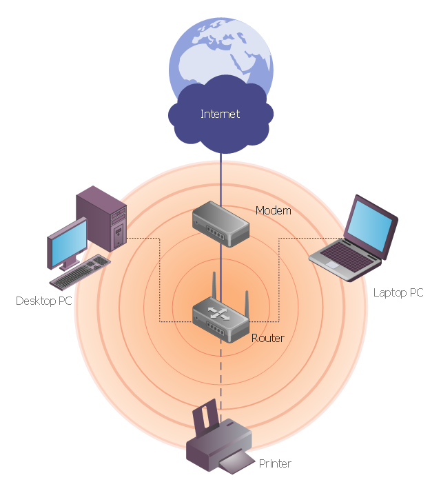
This network diagram sample depicts usage of wireless access point.
"In computer networking, a wireless access point (AP) is a device that allows wireless devices to connect to a wired network using Wi-Fi, or related standards. The AP usually connects to a router (via a wired network) as a standalone device, but it can also be an integral component of the router itself. ...
With the creation of the wireless Access Point (AP), network users are now able to add devices that access the network with few or no cables. An AP normally connects directly to a wired Ethernet connection and the AP then provides wireless connections using radio frequency links for other devices to utilize that wired connection. Most APs support the connection of multiple wireless devices to one wired connection. Modern APs are built to support a standard for sending and receiving data using, these radio frequencies. Those standards, and the frequencies they use are defined by the IEEE. Most APs use IEEE 802.11 standards." [Wireless access point. Wikipedia]
The wireless network diagram example "Wireless access point" was created using the ConceptDraw PRO diagramming and vector drawing software extended with the Wireless Networks solution from the Computer and Networks area of ConceptDraw Solution Park.
Wireless network diagram
"There are two definitions for wireless LAN roaming:
Internal Roaming (1): The Mobile Station (MS) moves from one access point (AP) to another AP within a home network because the signal strength is too weak. An authentication server (RADIUS) performs the re-authentication of MS via 802.1x (e.g. with PEAP). The billing of QoS is in the home network. A Mobile Station roaming from one access point to another often interrupts the flow of data among the Mobile Station and an application connected to the network. The Mobile Station, for instance, periodically monitors the presence of alternative access points (ones that will provide a better connection). At some point, based on proprietary mechanisms, the Mobile Station decides to re-associate with an access point having a stronger wireless signal. The Mobile Station, however, may lose a connection with an access point before associating with another access point. In order to provide reliable connections with applications, the Mobile Station must generally include software that provides session persistence.
External Roaming (2): The MS (client) moves into a WLAN of another Wireless Internet Service Provider (WISP) and takes their services (Hotspot). The user can independently of his home network use another foreign network, if this is open for visitors. There must be special authentication and billing systems for mobile services in a foreign network." [Wireless LAN. Wikipedia]
This Cisco roaming wireless local area network diagram example was created using the ConceptDraw PRO diagramming and vector drawing software extended with the Cisco Network Diagrams solution from the Computer and Networks area of ConceptDraw Solution Park.
WLAN diagram

Used Solutions
Hotel Network Topology Diagram


How to Create Network Diagrams
Cisco Products Additional. Cisco icons, shapes, stencils and symbols

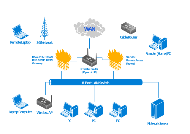
This wireless network diagram sample illustrates mobile data offloading.
"Mobile data offloading is the use of complementary network technologies for delivering data originally targeted for cellular networks. Rules triggering the mobile offloading action can be set by either an end-user (mobile subscriber) or an operator. The code operating on the rules resides in an end-user device, in a server, or is divided between the two. End users do data offloading for data service cost control and the availability of higher bandwidth. Operators do it to ease congestion of cellular networks. The main complementary network technologies used for mobile data offloading are Wi-Fi, femtocell and Integrated Mobile Broadcast." [Mobile data offloading. Wikipedia]
The wireless network diagram example "Mobile data offloading" was created using the ConceptDraw PRO diagramming and vector drawing software extended with the Wireless Networks solution from the Computer and Networks area of ConceptDraw Solution Park.
Wireless network diagram
Cisco Network Topology. Cisco icons, shapes, stencils and symbols

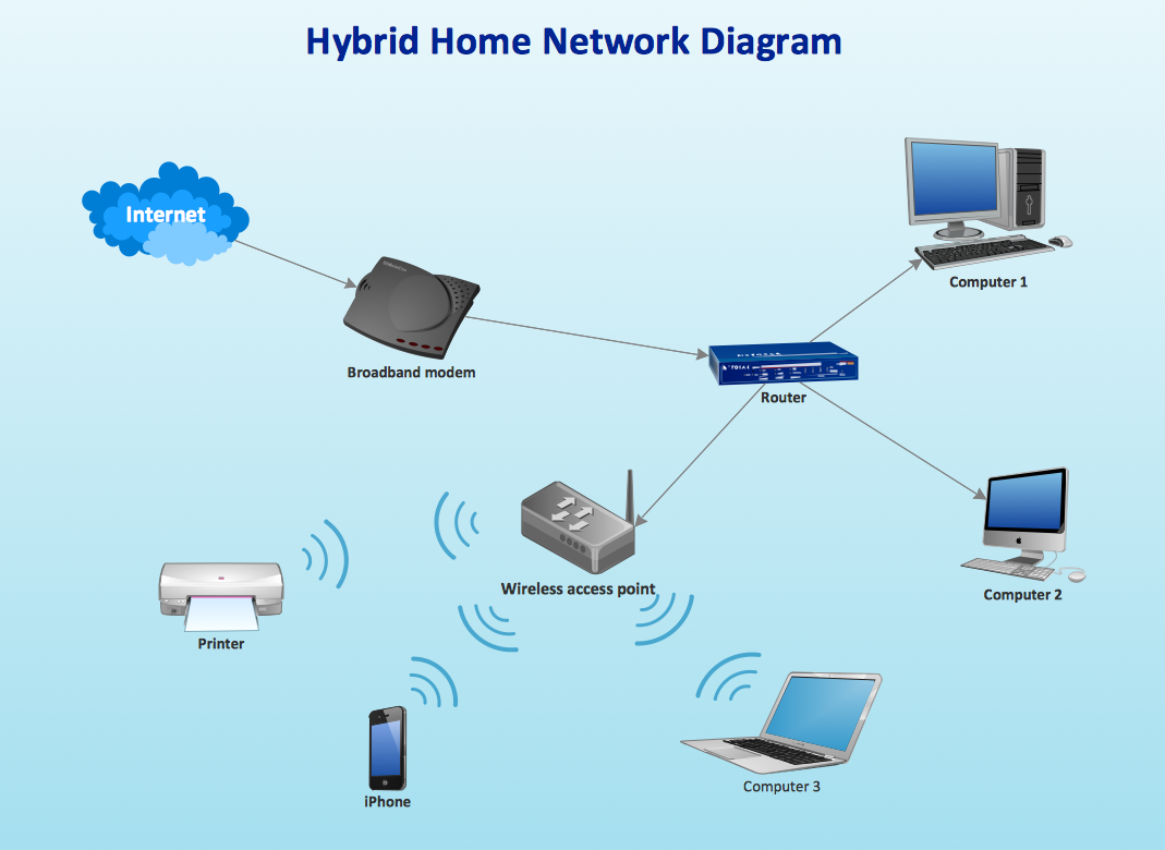
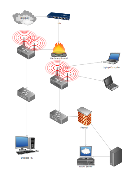
"A computer network diagram is a schematic depicting the nodes and connections amongst nodes in a computer network or, more generally, any telecommunications network. At different scales diagrams may represent various levels of network granularity. At the LAN level, individual nodes may represent individual physical devices, such as hubs or file servers, while at the WAN level, individual nodes may represent entire cities. In addition, when the scope of a diagram crosses the common LAN/ MAN/ WAN boundaries, representative hypothetical devices may be depicted instead of showing all actually existing nodes." [Computer network diagram. Wikipedia]
This computer network diagram example was created using the ConceptDraw PRO diagramming and vector drawing software extended with the Computer and Networks solution from the Computer and Networks area of ConceptDraw Solution Park.
This computer network diagram example was created using the ConceptDraw PRO diagramming and vector drawing software extended with the Computer and Networks solution from the Computer and Networks area of ConceptDraw Solution Park.
Network diagram
Wireless Network Topology

Guesthouse Network. WIFI network to my guest house

The vector stencils library "Cisco products additional" contains 141 symbols of computer network devices and equipment for drawing Cisco network diagrams.
The symbols example "Cisco products additional - Vector stencils library" was created using the ConceptDraw PRO diagramming and vector drawing software extended with the Cisco Network Diagrams solution from the Computer and Networks area of ConceptDraw Solution Park.
www.conceptdraw.com/ solution-park/ computer-networks-cisco
Protocol translator
CiscoWorks workstation
Access server

Workgroup director
Network management appliance
Storage Solution Engine (SSE)
-cisco-products-additional---vector-stencils-library.png--diagram-flowchart-example.png)
Software based router on file / application server
Cisco MeetingPlace Express
PC router card
Transpath
Bridge
IOS SLB
100BaseT hub
uBR910
CDDI-FDDI
PC adapter card
VIP
CSM-S
Terminal server
Route/Switch processor with Si
Route/Switch processor
PXF
AVS (Application Velicity System)
-cisco-products-additional---vector-stencils-library.png--diagram-flowchart-example.png)
Content engine (cache director)
-cisco-products-additional---vector-stencils-library.png--diagram-flowchart-example.png)
Cisco file engine
Management engine (ME 1100)
-cisco-products-additional---vector-stencils-library.png--diagram-flowchart-example.png)
PC with router-based software
PC with software
ASIC processor
Generic processor
Switch processor
Cisco 5500 family
Multi-switch device
IP transport concentrator
ITP
Cisco CA
Voice gateway
BBSM
ATA
SIP Proxy server

MicroWeb server

NetRanger
Cisco 6920 RateMux
NetSonar
Cisco 1000
IP
System controller
ACE
Voice-enabled access server (voice-enabled communications server)
-cisco-products-additional---vector-stencils-library.png--diagram-flowchart-example.png)
Directory server

Cisco 4310 end office system
ADM
FireWall Service Module (FWSM)
-cisco-products-additional---vector-stencils-library.png--diagram-flowchart-example.png)
Cisco Unity Express
Cisco Unity Server
Centri firewall
Cisco Security Manager

Data switch processor (AKA data center switch)
-cisco-products-additional---vector-stencils-library.png--diagram-flowchart-example.png)
Cisco MP
IOS firewall
PIX firewall, right

PIX firewall, left
CallManager

Cisco 6700 Series
MGX 8240
MGX 8220
MGX 8260
DSLAM
Cisco 6732 access server
Cisco 6701
H.323
Access gateway
ICS 7750
VPN concentrator
SSL terminator
CDM (Content Distribution Manager)
-cisco-products-additional---vector-stencils-library.png--diagram-flowchart-example.png)
Cisco 15200
Cisco 15800
Content Service Module
Content Transformation Engine (CTE)
-cisco-products-additional---vector-stencils-library.png--diagram-flowchart-example.png)
Cisco VN 2900
Cisco VN 5900
Cisco VN 5902
Cisco Unified Presence Server
ICM
PC card
Access point
Dual mode access point
EtherClient
Tablet
Wireless transport
Wireless bridge
Lightweight single radio access point
Lightweight Double Radio Access Point
WLAN controller
Wi-Fi tag
Wireless location appliance
Wireless connectivity

WiSM
Mesh AP
SC2200 Signaling Controller
Virtual Switch Controller (VSC3000)
-cisco-products-additional---vector-stencils-library.png--diagram-flowchart-example.png)
VS C3000 or SC2200 host
BTS 10200 Softswitch
Detector
IP/TV content manager
IP/TV broadcast server
Universal gateway

Generic softswitch
Generic Softswitch (blue)
-cisco-products-additional---vector-stencils-library.png--diagram-flowchart-example.png)
Guard
Mobile access router
Carrier Routing System (CRS)
-cisco-products-additional---vector-stencils-library.png--diagram-flowchart-example.png)
FC storage
Intelliswitch Stack
Service control
UPC (Unified Personal Communicator)
-cisco-products-additional---vector-stencils-library.png--diagram-flowchart-example.png)
PMC
IP communicator

Streamer
Vault
DWDM filter
DWDM ring
DWDM network line
Streamer (half-full)
-cisco-products-additional---vector-stencils-library.png--diagram-flowchart-example.png)
Vault (half-full)
-cisco-products-additional---vector-stencils-library.png--diagram-flowchart-example.png)
Data center switch, reversed
Scanner
10GE/FCoE
car
CUBE
Director-class fibre channel director
Fibre channel disk subsystem
Fibre channel fabric switch
Generic gateway
Handheld
Internet streamer
JBOD
MAS gateway
Mesh AP
Mobile streamer
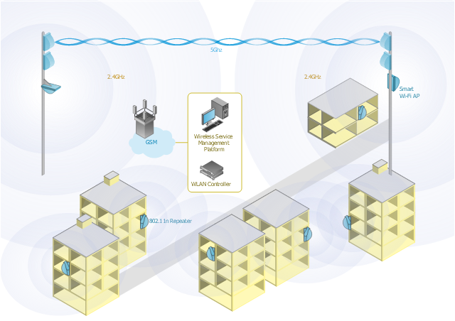
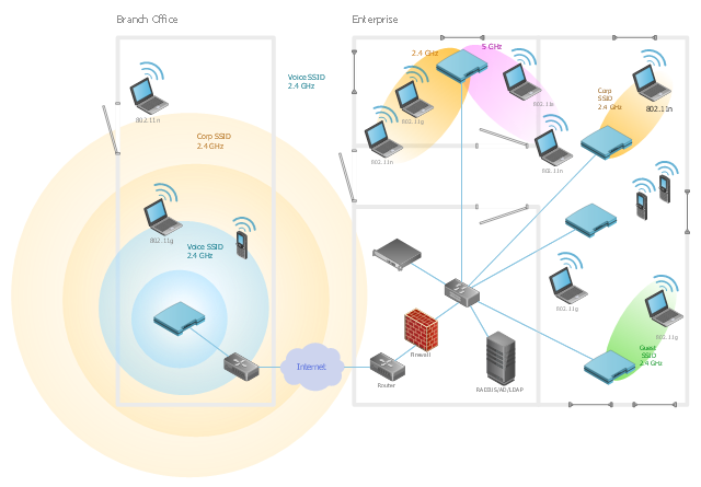
This wireless network diagram sample shows ultra high performance WLANs.
"A wireless local area network (WLAN) links two or more devices using some wireless distribution method (typically spread-spectrum or OFDM radio), and usually providing a connection through an access point to the wider Internet. This gives users the ability to move around within a local coverage area and still be connected to the network. Most modern WLANs are based on IEEE 802.11 standards, marketed under the Wi-Fi brand name. WLANs were once called LAWNs (for local area wireless network) by the Department of Defense." [Wireless LAN. Wikipedia]
The wireless network diagram example "Ultra high performance WLANs" was created using the ConceptDraw PRO diagramming and vector drawing software extended with the Wireless Networks solution from the Computer and Networks area of ConceptDraw Solution Park.
Wireless network diagram
Guesthouse Network
Hotel Network Topology Diagram. Hotel Guesthouse WiFi Network

Network Gateway Router


- Wireless access point - Network diagram | Roaming wireless local ...
- Using Both Wired and Wireless Connections | Wireless access point ...
- Wireless access point - Network diagram
- Network Printer | Network diagrams with ConceptDraw PRO ...
- Wireless Networks | Wireless Network Diagram Examples | How to ...
- Wireless access point - Network diagram | Roaming wireless local ...
- Wireless access point - Network diagram | Network Glossary ...
- Point to Point Network Topology | Wireless access point - Network ...
- Wireless Networks | Wireless Network Diagram Examples | Wireless ...
- Star Network Topology | Wireless access point - Network diagram ...
- Wireless Networks | Wireless Network Topology | Wireless access ...
- Hotel Network Topology Diagram | Wireless access point - Network ...
- Wireless access point - Network diagram | Mesh Network Topology ...
- Network Glossary Definition | Wireless access point - Network ...
- Hotel Network Topology Diagram . Hotel Guesthouse WiFi Network ...
- Wireless router network diagram | Cisco Routers. Cisco icons ...
- Hotel Network Topology Diagram . Hotel Guesthouse WiFi Network ...
- Wireless router network diagram | Wireless networks - Vector ...
- Access Point Topology Releted To Wifi
- Long-range Wi-Fi network diagram | Wireless networks - Vector ...