Diagramming Software for Design UML Activity Diagrams


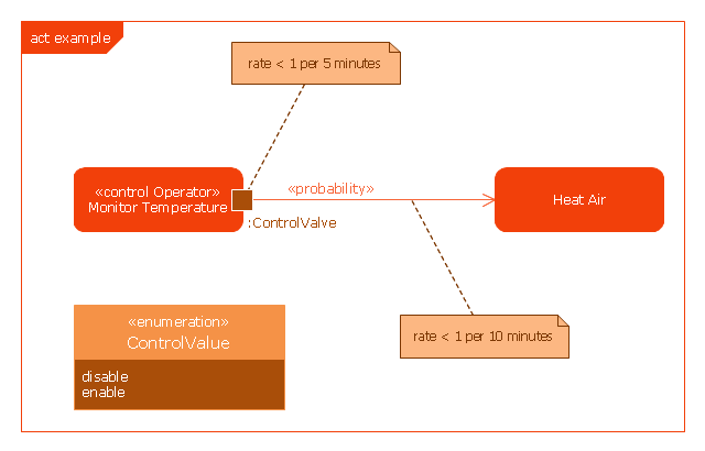
This example was drawn on the base of SysML activity diagram on the page 8 of "SysML Modelling Language explained" document from the Official OMG SysML site.
"The activity diagram represents steps of a process, often making use of “input and output pins” that respectively correspond to the element type required as the input of an activity or action, and the element generated as an output.
If an action or activity corresponds to a block operation, it is possible to ensure that the types of the input and output of this activity are consistent with the block operation signature.
All the activity diagrams definitions used in UML also apply to SysML.
SysML has added a couple of extensions:
- With UML, control can only enable actions to start. SysML extends control to support disabling of actions that are already executing.
- Definition of the flow rate : continuous or discrete
- Definition of the rate and probability on the control or object flows"
[omgsysml.org/ SysML_ Modelling_ Language_ explained-finance.pdf]
The example "SysML activity diagram" was drawn using the ConceptDraw PRO diagramming and vector drawing software extended with the SysML solution from the Software Development area of ConceptDraw Solution Park.
Example of SysML activity diagram
UML Activity Diagram. Design Elements

UML Activity Diagram

This vector stencils library contains 47 SysML activity diagram symbols.
Use it to design your SysML activity diagrams using ConceptDraw PRO diagramming and vector drawing software.
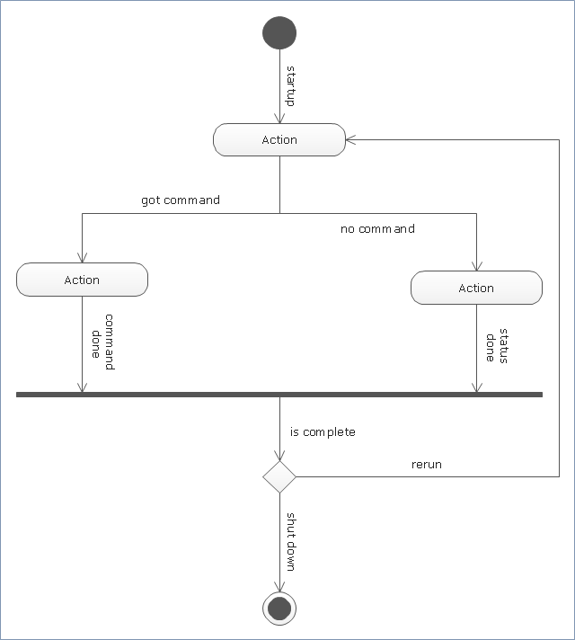
"Activity diagrams are constructed from a limited number of shapes, connected with arrows. The most important shape types:
- rounded rectangles represent actions;
- diamonds represent decisions;
- bars represent the start (split) or end (join) of concurrent activities;
- a black circle represents the start (initial state) of the workflow;
- an encircled black circle represents the end (final state).
Arrows run from the start towards the end and represent the order in which activities happen." [Activity diagram. Wikipedia]
The vector stencils library "Activity diagram" is included in the SysML solution from the Software Development area of ConceptDraw Solution Park.
Use it to design your SysML activity diagrams using ConceptDraw PRO diagramming and vector drawing software.
"Activity diagrams are constructed from a limited number of shapes, connected with arrows. The most important shape types:
- rounded rectangles represent actions;
- diamonds represent decisions;
- bars represent the start (split) or end (join) of concurrent activities;
- a black circle represents the start (initial state) of the workflow;
- an encircled black circle represents the end (final state).
Arrows run from the start towards the end and represent the order in which activities happen." [Activity diagram. Wikipedia]
The vector stencils library "Activity diagram" is included in the SysML solution from the Software Development area of ConceptDraw Solution Park.
Action

Call behavior action

Accept event action

Accept time event action

Send signal action

Activity

Activity final node

Flow final node

Activity parameter node

Control operator node

Control operator - frame

Decision/Merge node

Fork/Join node

Initial node

isControl

isStream

isStream 2

isStream 3

Local precondition

Local postcondition

NoBuffer

Object node

Object node 2

Optional

Optional 2

OverWrite

Parameter set

Parameter set 2

Probability

Probability 2

Rate

Rate 2

Rate 3

Rate 4

Rate 5

Rate 6

Control flow

Control flow 2

Object flow

Object flow 2

Probability path

Rate path

In block definition diagram, activity, association

Activity partition

Activity partition - action

Interruptible activity region

Structured activity node

Data Flow Diagram

UML Diagram Types List

Data Modeling Diagram

"An activity in Unified Modeling Language (UML) is a major task that must take place in order to fulfill an operation contract. Activities can be represented in activity diagrams.
An activity can represent:
(1) The invocation of an operation.
(2) A step in a business process.
(3) An entire business process.
Activities can be decomposed into subactivities, until at the bottom we find atomic actions.
The underlying conception of an activity has changed between UML 1.5 and UML 2.0. In UML 2.0 an activity is no longer based on the state-chart rather it is based on a Petri net like coordination mechanism. There the activity represents user-defined behavior coordinating actions. Actions in turn are pre-defined (UML offers a series of actions for this)." [Activity (UML). Wikipedia]
The template "UML activity diagram" for the ConceptDraw PRO diagramming and vector drawing software is included in the Rapid UML solution from the Software Development area of ConceptDraw Solution Park.
www.conceptdraw.com/ solution-park/ software-uml
UML activity diagram
IDEF0 Flowchart Symbols

- Diagramming Software for Design UML Activity Diagrams | UML ...
- UML activity diagram - Cash withdrawal from ATM | ATM UML ...
- Bank Activity Diagram
- SYSML | Rapid UML | ATM UML Diagrams | Activity Diagram For ...
- UML Activity Diagram | Diagramming Software for Design UML ...
- UML activity diagram - User registration
- Activity Diagram For Supermarket Management System Pdf
- Activity Diagram For Banking System
- Activity Diagram Elaborating Accounting Office
- Design elements - Activity diagram | Design elements - UML activity ...