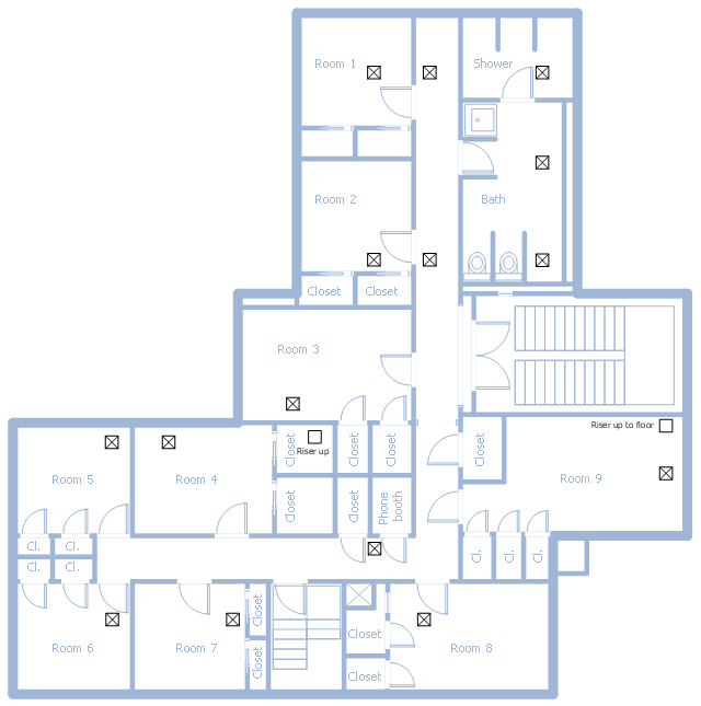
This school HVAC plan sample represent layout of air conditioning ductwork inlets and outlets.
"Air conditioning (often referred to as A/ C or AC) is the process of altering the properties of air (primarily temperature and humidity) to more comfortable conditions, typically with the aim of distributing the conditioned air to an occupied space such as a building or a vehicle to improve thermal comfort and indoor air quality. In common use, an air conditioner is a device that removes heat from the air inside a building or vehicle, thus lowering the air temperature. The cooling is typically achieved through a refrigeration cycle, but sometimes evaporation or free cooling is used. Air conditioning systems can also be made based on desiccants." [Air conditioning. Wikipedia]
The fllor plan example "School HVAC plan" was created using the ConceptDraw DIAGRAM diagramming and vector drawing software extended with the HVAC Plans solution from the Building Plans area of ConceptDraw Solution Park.
Floor plan
Mechanical Drawing Symbols

- HVAC Plans | How to Create a HVAC Plan | Air handler- HVAC plan ...
- How to Create a HVAC Plan | Design elements - HVAC ductwork ...
- Hvac Duct Design Example
- Ductwork layout | HVAC Plans | Design elements - HVAC ductwork ...
- Ductwork layout | House tap water supply | School HVAC plan | How ...
- Single Line Diagram Of Hvac Water Cooler System
- Plumbing and Piping Plans | School HVAC plan | House water ...
- Hvac Equipment Layout
- Air Conditioner Engineer Drawing
- RCP - HVAC layout | HVAC Plans | Plumbing and Piping Plans ...