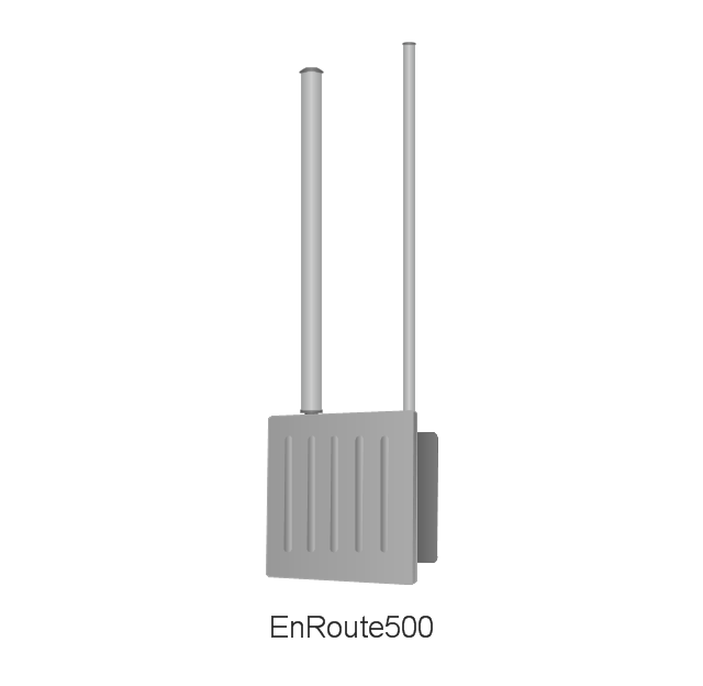
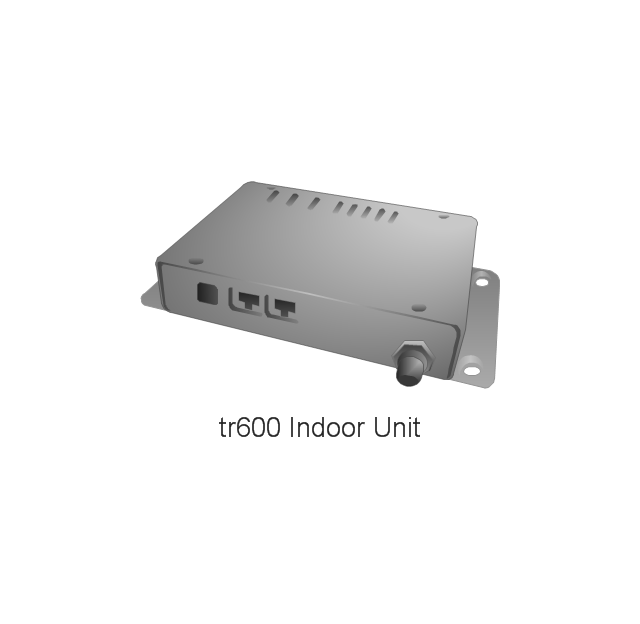
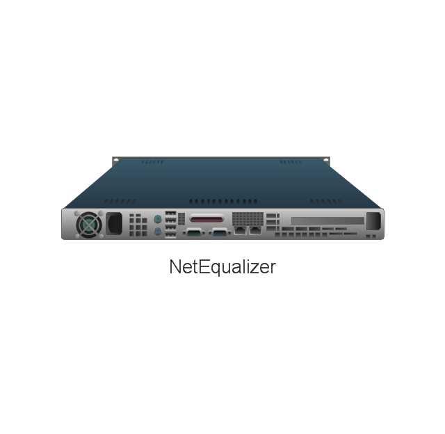
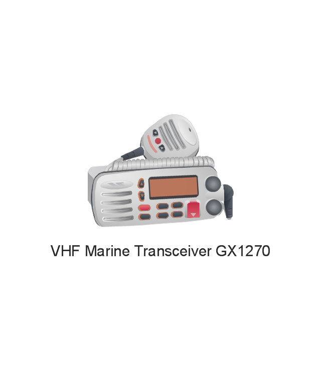
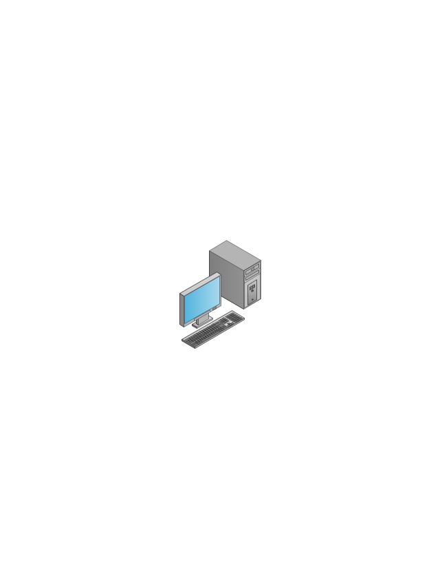
The vector stencils library "Telecommunication networks" contains 32 clipart images of telecommunication network devices and equipment for drawing telecom network diagrams.
"A telecommunications network is a collection of terminal nodes, links and any intermediate nodes which are connected so as to enable telecommunication between the terminals.
The transmission links connect the nodes together. The nodes use circuit switching, message switching or packet switching to pass the signal through the correct links and nodes to reach the correct destination terminal.
Each terminal in the network usually has a unique address so messages or connections can be routed to the correct recipients. The collection of addresses in the network is called the address space." [Telecommunications network. Wikipedia]
The clip art example "Telecommunication networks - Vector stencils library" was created using the ConceptDraw PRO diagramming and vector drawing software extended with the Telecommunication Network Diagrams solution from the Computer and Networks area of ConceptDraw Solution Park.
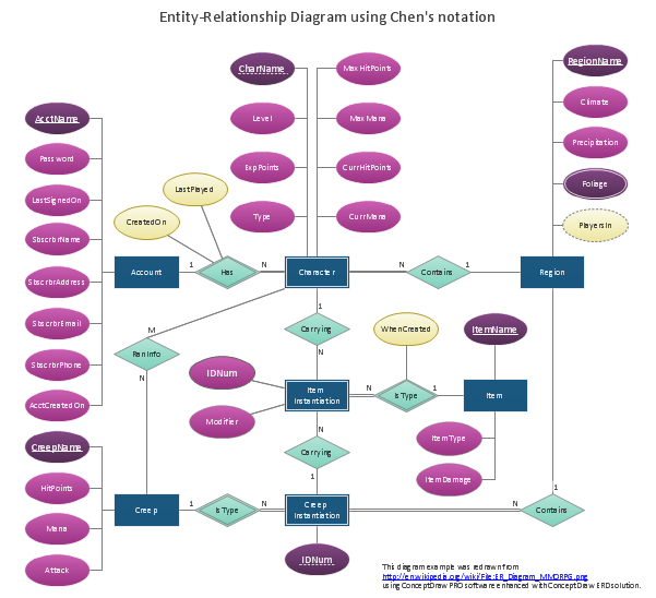
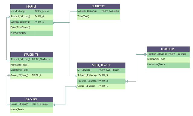
"An ER model is an abstract way of describing a database. In the case of a relational database, which stores data in tables, some of the data in these tables point to data in other tables - for instance, your entry in the database could point to several entries for each of the phone numbers that are yours. The ER model would say that you are an entity, and each phone number is an entity, and the relationship between you and the phone numbers is 'has a phone number'. Diagrams created to design these entities and relationships are called entity–relationship diagrams or ER diagrams.
Using the three schema approach to software engineering, there are three levels of ER models that may be developed. ...
Conceptual data model ... is the highest level ER model in that it contains the least granular detail but establishes the overall scope of what is to be included within the model set.
Logical ER model ... contains more detail than the conceptual ER model. In addition to master data entities, operational and transactional data entities are now defined.
The physical ER model is normally developed to be instantiated as a database. Therefore, each physical ER model must contain enough detail to produce a database and each physical ER model is technology dependent since each database management system is somewhat different.
Physical model ... is normally forward engineered to instantiate the structural metadata into a database management system as relational database objects such as database tables, database indexes such as unique key indexes, and database constraints such as a foreign key constraint or a commonality constraint." [Entity–relationship model. Wikipedia]
This crow's foot entity-relationship diagram (ERD) example "Educational data base" was created using the ConceptDraw PRO diagramming and vector drawing software extended with the Entity-Relationship Diagram (ERD) solution from the Software Development area of ConceptDraw Solution Park.
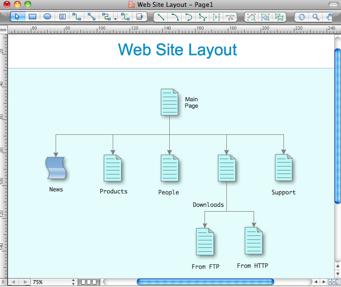
Internet solutions with ConceptDraw PRO
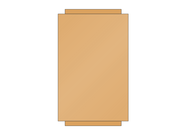
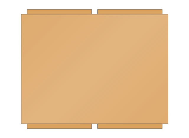
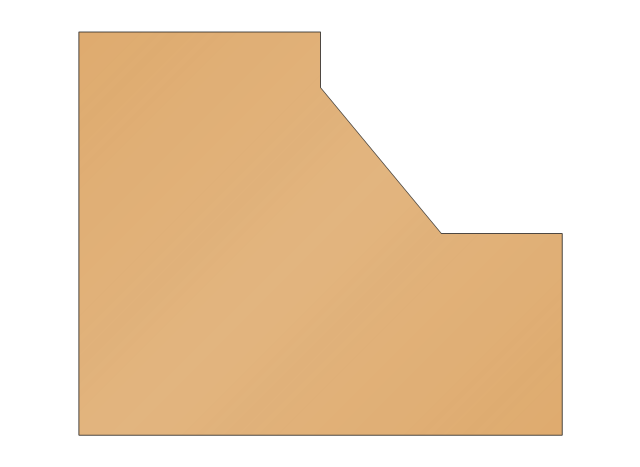
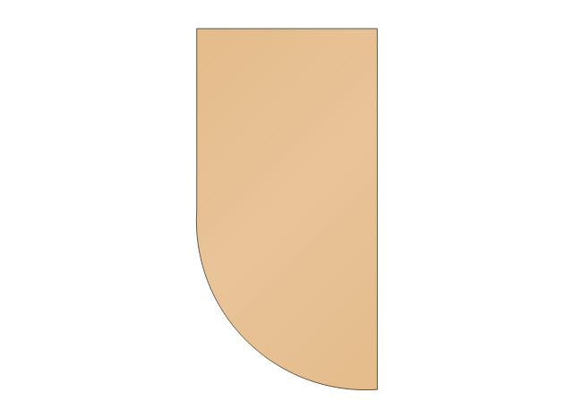
ConceptDraw is a good means of visualization of information of any kind as it features powerful graphic capabilities. The conception of using ConceptDraw and open formats by the programs that work with Internet can be used for displaying any data and any structure in Internet.The vector stencils library "Cabinets and bookcases" contains 41 shapes of cabinets and bookcases.
Use it for drawing floor plans in the ConceptDraw PRO diagramming and vector drawing software extended with the Floor Plans solution from the Building Plans area of ConceptDraw Solution Park.
www.conceptdraw.com/ solution-park/ floor-plans
Use it for drawing floor plans in the ConceptDraw PRO diagramming and vector drawing software extended with the Floor Plans solution from the Building Plans area of ConceptDraw Solution Park.
www.conceptdraw.com/ solution-park/ floor-plans
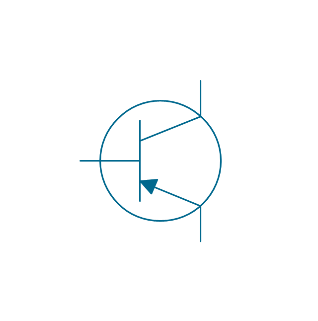
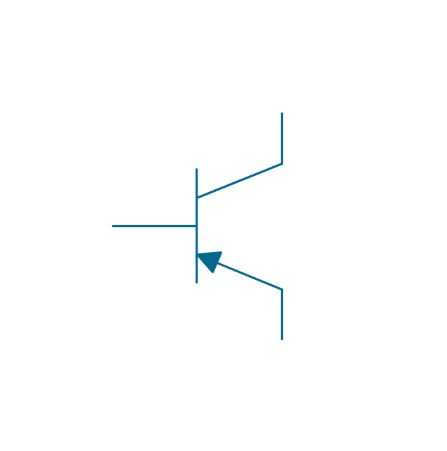
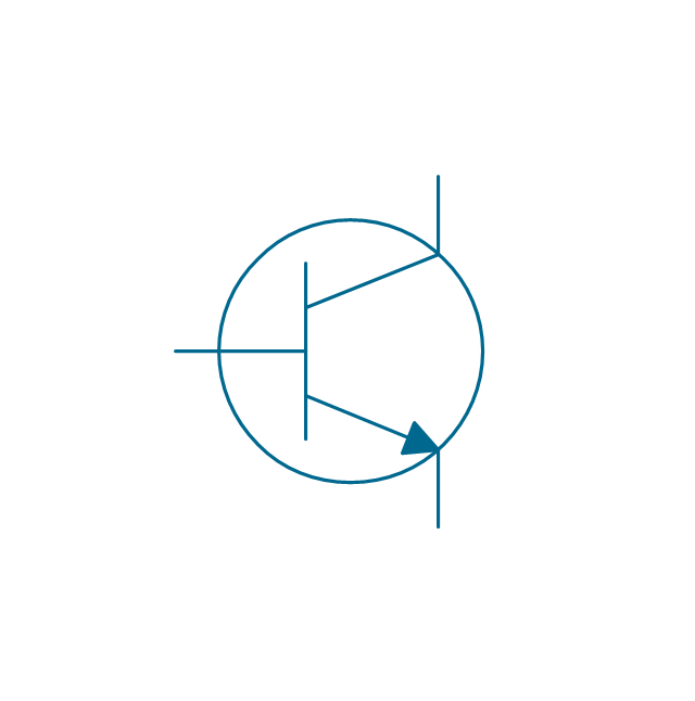
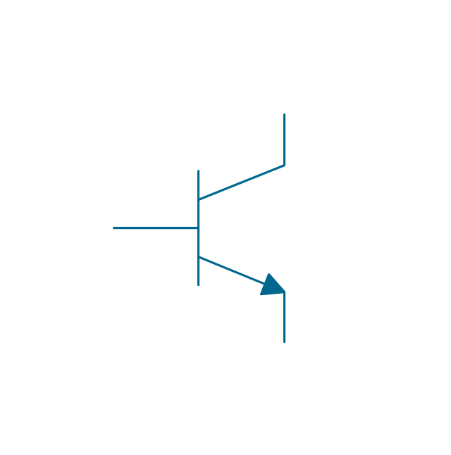
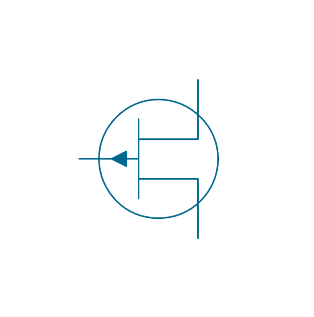
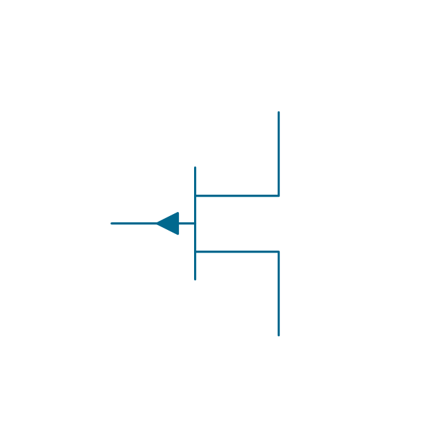
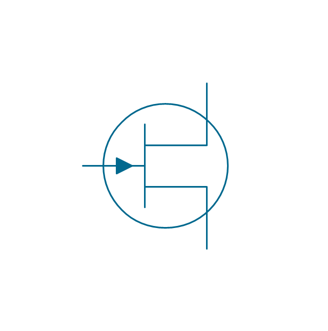
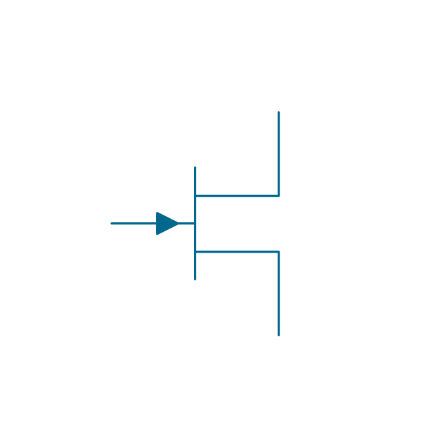
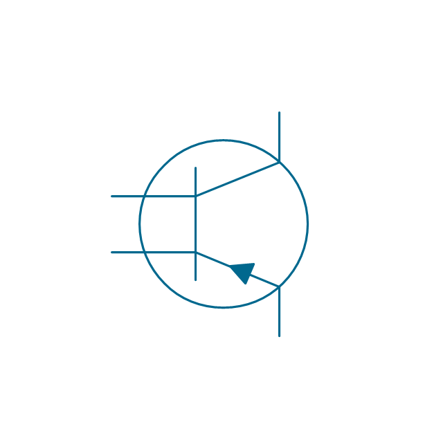
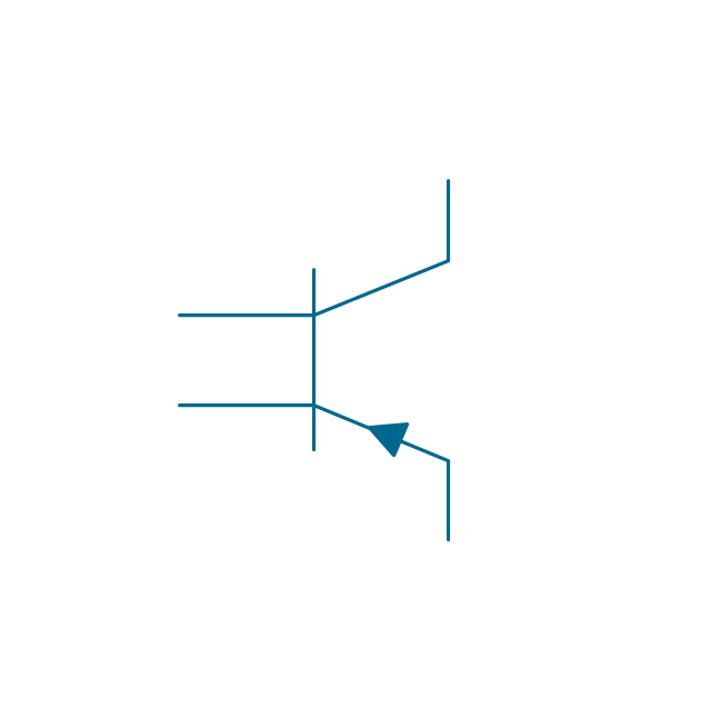
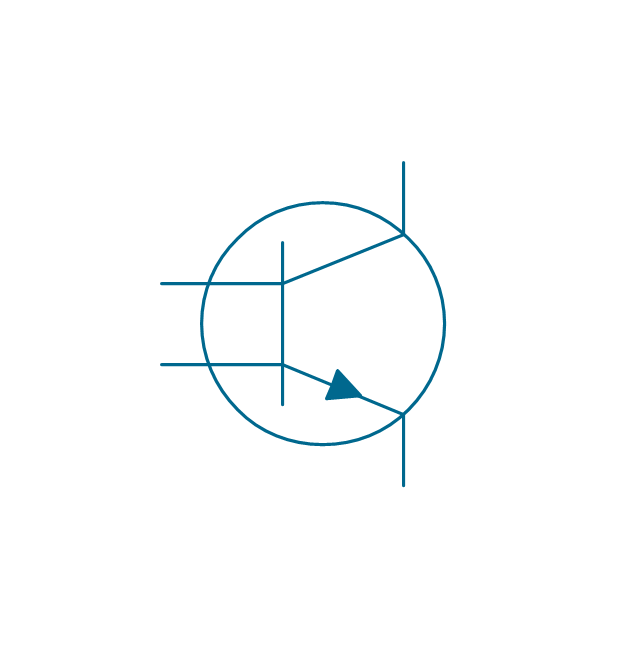
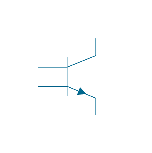
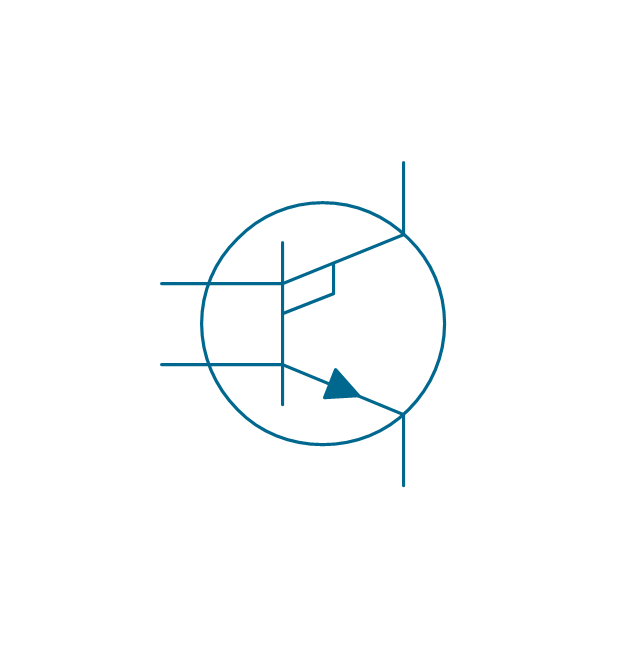
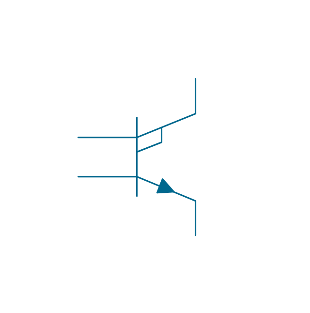
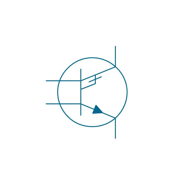
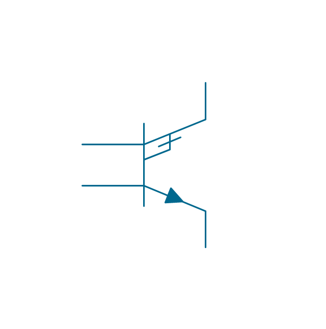
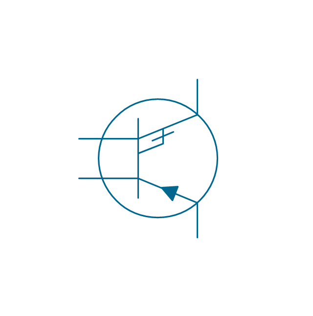
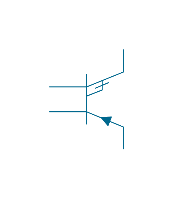
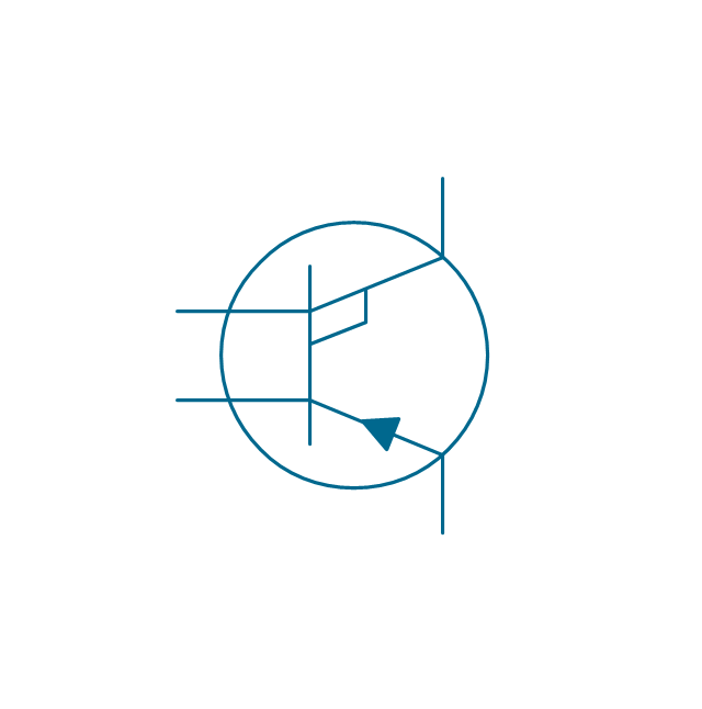
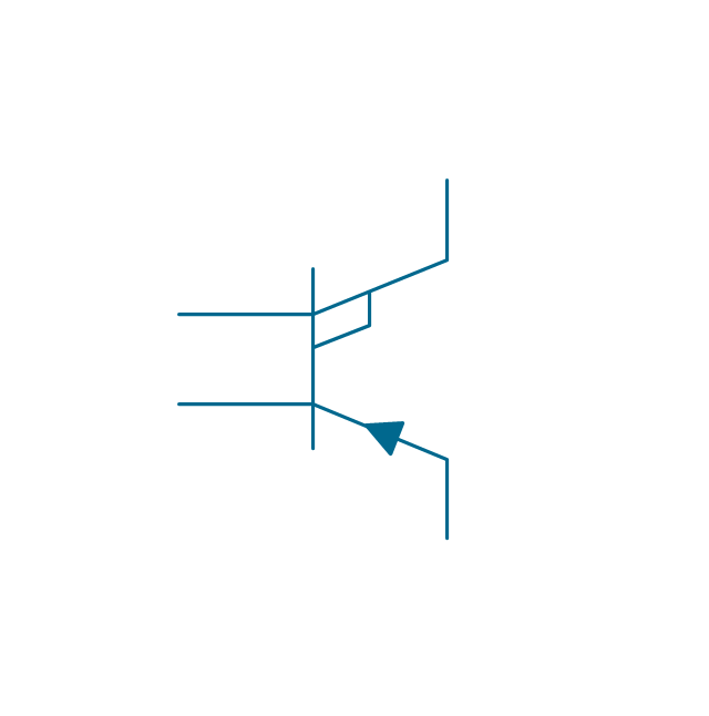
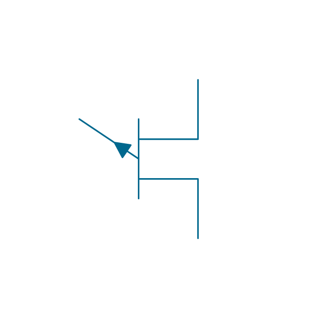
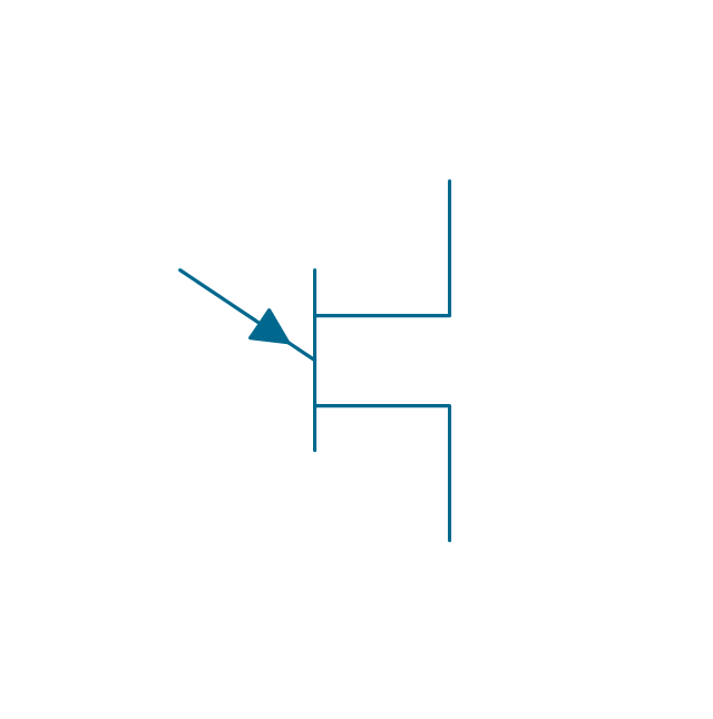
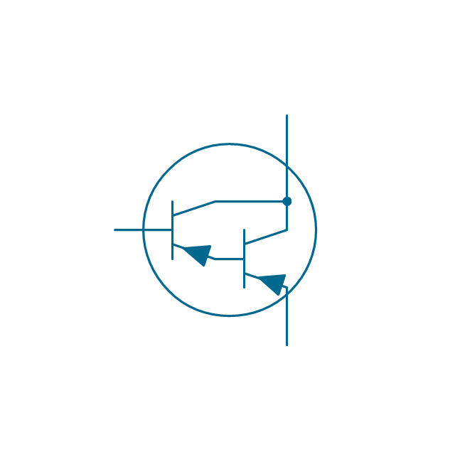
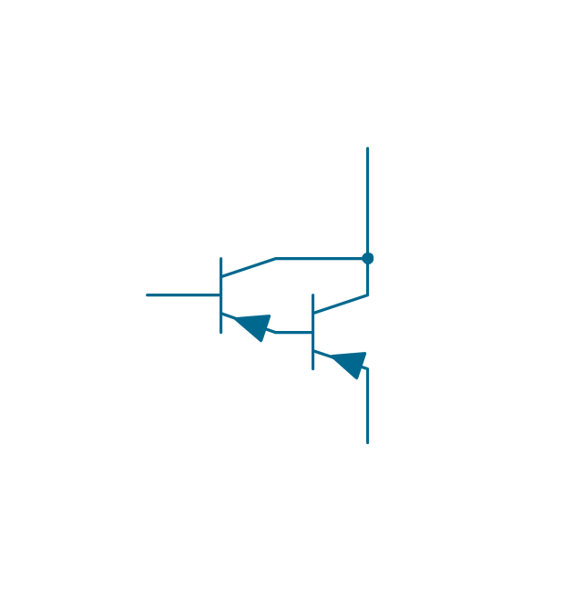
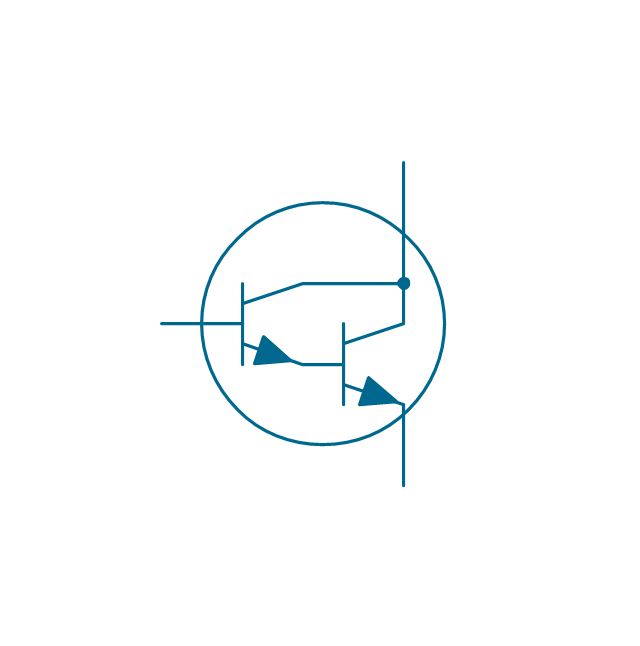
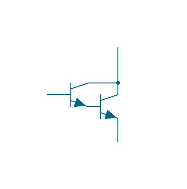
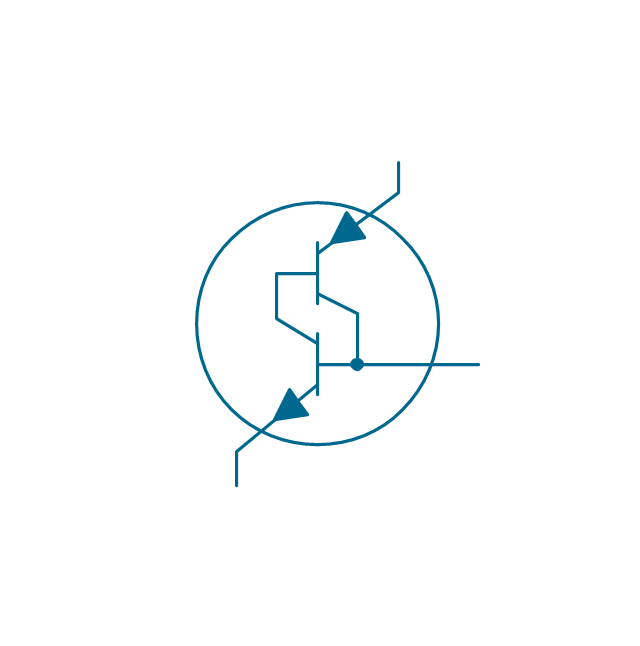
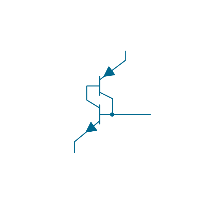
The vector stencils library "Transistors" contains 30 symbols of transistors.
Use these shapes for drawing electronic schematics and circuit diagrams in the ConceptDraw PRO diagramming and vector drawing software extended with the Electrical Engineering solution from the Engineering area of ConceptDraw Solution Park.
www.conceptdraw.com/ solution-park/ engineering-electrical
Use these shapes for drawing electronic schematics and circuit diagrams in the ConceptDraw PRO diagramming and vector drawing software extended with the Electrical Engineering solution from the Engineering area of ConceptDraw Solution Park.
www.conceptdraw.com/ solution-park/ engineering-electrical
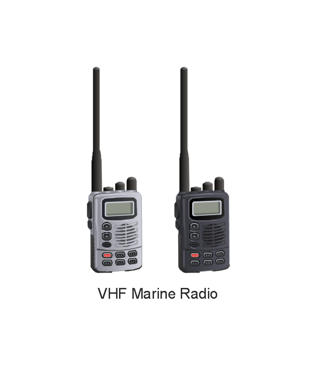
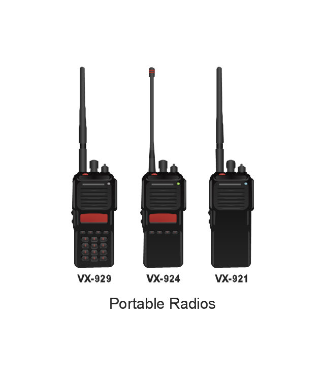
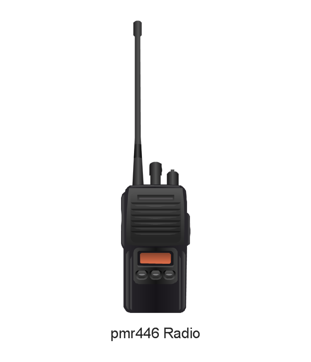
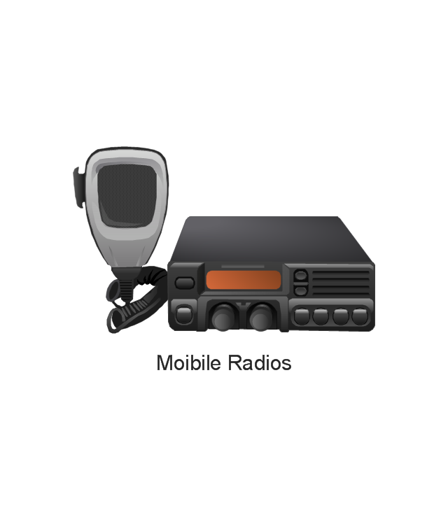
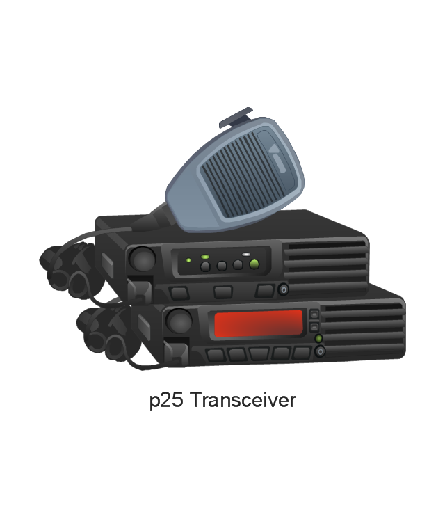
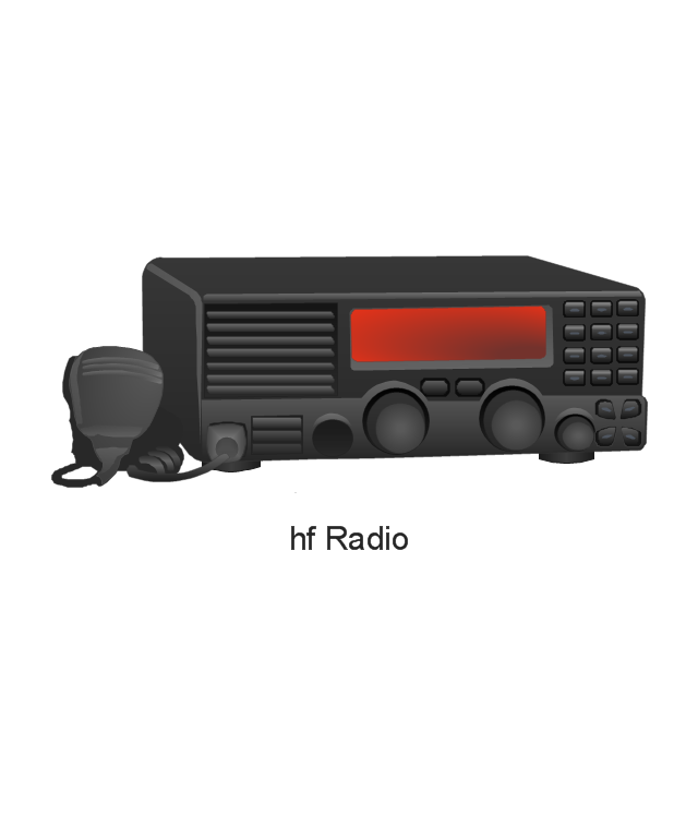
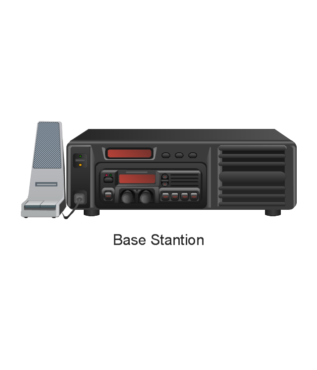
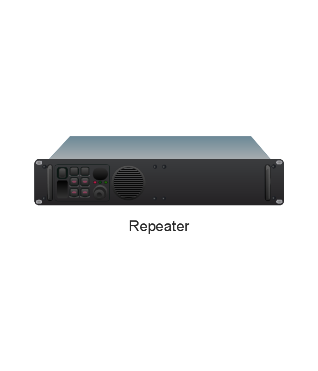
The vector stencils library "Vertex" contains 9 clipart icons of Vertex devices for drawing computer network diagrams and telecommunication equipment layouts.
"Vertex Standard is exclusively focused in offering a broad portfolio of analogue and digital two-way radios...
Products: Portable Radios, Mobile Radios, Repeaters / Base Stations, HF SSB Radios, APCO P25 Radios, Digital TDMA Radios (DMR), Trunking Radios." [vertex-standard-emea.com]
The clip art example "Vertex - Vector stencils library" was created using the ConceptDraw PRO diagramming and vector drawing software extended with the Telecommunication Network Diagrams solution from the Computer and Networks area of ConceptDraw Solution Park.
www.conceptdraw.com/ solution-park/ computer-networks-telecommunication
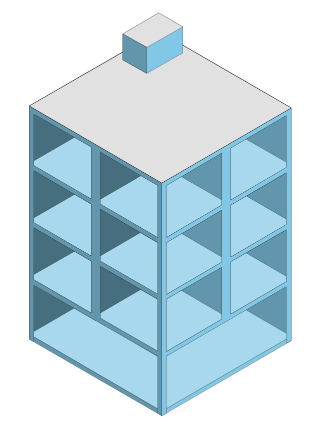
The vector stencils library "Cabinets and bookcases" contains 41 shapes of cabinets and bookcases.
Use it for drawing floor plans in the ConceptDraw PRO diagramming and vector drawing software extended with the Floor Plans solution from the Building Plans area of ConceptDraw Solution Park.
www.conceptdraw.com/ solution-park/ floor-plans
Use it for drawing floor plans in the ConceptDraw PRO diagramming and vector drawing software extended with the Floor Plans solution from the Building Plans area of ConceptDraw Solution Park.
www.conceptdraw.com/ solution-park/ floor-plans
The vector stencils library "Telecommunication networks" contains 32 clipart images of telecommunication network devices and equipment for drawing telecom network diagrams.
"A telecommunications network is a collection of terminal nodes, links and any intermediate nodes which are connected so as to enable telecommunication between the terminals.
The transmission links connect the nodes together. The nodes use circuit switching, message switching or packet switching to pass the signal through the correct links and nodes to reach the correct destination terminal.
Each terminal in the network usually has a unique address so messages or connections can be routed to the correct recipients. The collection of addresses in the network is called the address space." [Telecommunications network. Wikipedia]
The clip art example "Telecommunication networks - Vector stencils library" was created using the ConceptDraw PRO diagramming and vector drawing software extended with the Telecommunication Network Diagrams solution from the Computer and Networks area of ConceptDraw Solution Park.
"A telecommunications network is a collection of terminal nodes, links and any intermediate nodes which are connected so as to enable telecommunication between the terminals.
The transmission links connect the nodes together. The nodes use circuit switching, message switching or packet switching to pass the signal through the correct links and nodes to reach the correct destination terminal.
Each terminal in the network usually has a unique address so messages or connections can be routed to the correct recipients. The collection of addresses in the network is called the address space." [Telecommunications network. Wikipedia]
The clip art example "Telecommunication networks - Vector stencils library" was created using the ConceptDraw PRO diagramming and vector drawing software extended with the Telecommunication Network Diagrams solution from the Computer and Networks area of ConceptDraw Solution Park.
The vector stencils library "Transistors" contains 30 symbols of transistors.
Use these shapes for drawing electronic schematics and circuit diagrams in the ConceptDraw PRO diagramming and vector drawing software extended with the Electrical Engineering solution from the Engineering area of ConceptDraw Solution Park.
www.conceptdraw.com/ solution-park/ engineering-electrical
Use these shapes for drawing electronic schematics and circuit diagrams in the ConceptDraw PRO diagramming and vector drawing software extended with the Electrical Engineering solution from the Engineering area of ConceptDraw Solution Park.
www.conceptdraw.com/ solution-park/ engineering-electrical
The vector stencils library "Vertex" contains 9 clipart icons of Vertex devices for drawing computer network diagrams and telecommunication equipment layouts.
"Vertex Standard is exclusively focused in offering a broad portfolio of analogue and digital two-way radios...
Products: Portable Radios, Mobile Radios, Repeaters / Base Stations, HF SSB Radios, APCO P25 Radios, Digital TDMA Radios (DMR), Trunking Radios." [vertex-standard-emea.com]
The clip art example "Vertex - Vector stencils library" was created using the ConceptDraw PRO diagramming and vector drawing software extended with the Telecommunication Network Diagrams solution from the Computer and Networks area of ConceptDraw Solution Park.
www.conceptdraw.com/ solution-park/ computer-networks-telecommunication
"Vertex Standard is exclusively focused in offering a broad portfolio of analogue and digital two-way radios...
Products: Portable Radios, Mobile Radios, Repeaters / Base Stations, HF SSB Radios, APCO P25 Radios, Digital TDMA Radios (DMR), Trunking Radios." [vertex-standard-emea.com]
The clip art example "Vertex - Vector stencils library" was created using the ConceptDraw PRO diagramming and vector drawing software extended with the Telecommunication Network Diagrams solution from the Computer and Networks area of ConceptDraw Solution Park.
www.conceptdraw.com/ solution-park/ computer-networks-telecommunication
HelpDesk
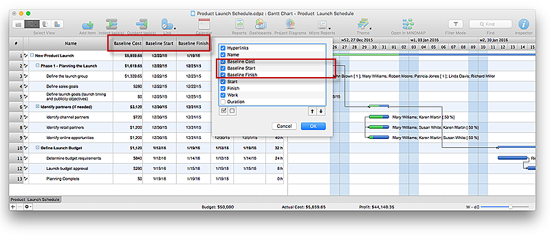
How to Set a Project Baseline Using ConceptDraw PROJECT
Project baseline in ConceptDraw PROJECT is excellent forguiding the execution of the current project and can be useful for further projects.The vector stencils library "Wireless networks" contains 82 icon symbols for drawing wireless computer network diagrams and equipment layout plans.
"A wireless network is any type of computer network that uses wireless data connections for connecting network nodes.
Wireless networking is a method by which homes, telecommunications networks and enterprise (business) installations avoid the costly process of introducing cables into a building, or as a connection between various equipment locations.
Wireless telecommunications networks are generally implemented and administered using radio communication. This implementation takes place at the physical level (layer) of the OSI model network structure.
Examples of wireless networks include cell phone networks, Wi-Fi local networks and terrestrial microwave networks." [Wireless network. Wikipedia]
The clip art example "Wireless networks - Vector stencils library" was created using the ConceptDraw PRO diagramming and vector drawing software extended with the Wireless Networks solution from the Computer and Networks area of ConceptDraw Solution Park.
www.conceptdraw.com/ solution-park/ wireless-networks
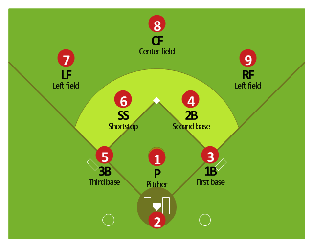
"Baseball is unlike most other competitive sports in that the defense is given control of the ball. Additionally, the number of players on the field at any given time is lopsided in favor of the defense which always has nine players on the field; the offense has between one and four. ...
Each play starts with the ball in the hands of the pitcher, whose job as a member of the defense is to use his skills to somehow prevent the batter from reaching base. The pitcher throws the ball toward the catcher, whose must catch the pitched ball if it is not hit by the batter. In each half-inning, the defense attempts to force three outs.
There are three basic ways in which an out can occur: 1.) If three strikes are recorded against the batter, 2.) if a ball hit by a batter is caught by a defensive player before it hits the ground, or 3.) if a runner who is between bases or has not reached a base to which he is forced is put out by a defensive player in possession of the ball.
If the batter manages to hit the ball, all nine defensive players become active and use the ball in attempting to prevent the batter from reaching base and runners already on base from advancing or scoring. while the offense is busy attempting to move runners around the baseball diamond toward home plate, the defense uses the ball in various ways to achieve outs.
If the defense forces three outs, their team is moved into the offensive role. The exception is if it is the ninth or an extra inning and they are ahead, in which case, the game ends and the defensive team wins." [Defense (sports). Wikipedia]
The baseball positions diagram example "Baseball defence positions" was created using the ConceptDraw PRO diagramming and vector drawing software extended with the Baseball solution from the Sport area of ConceptDraw Solution Park.
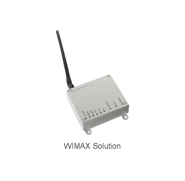
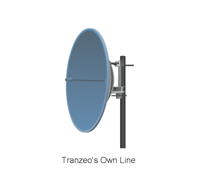
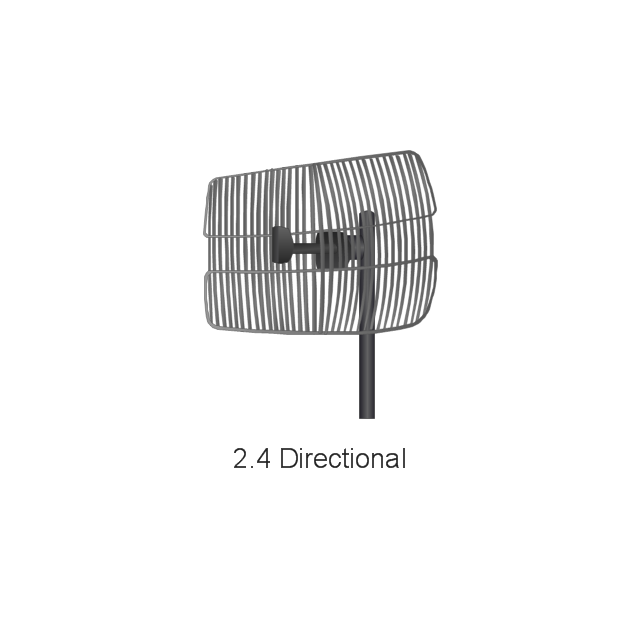
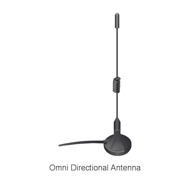
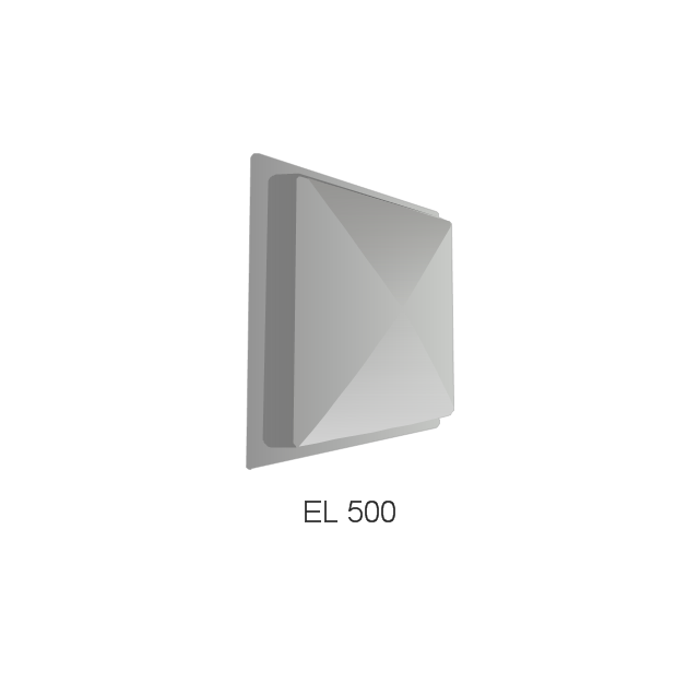
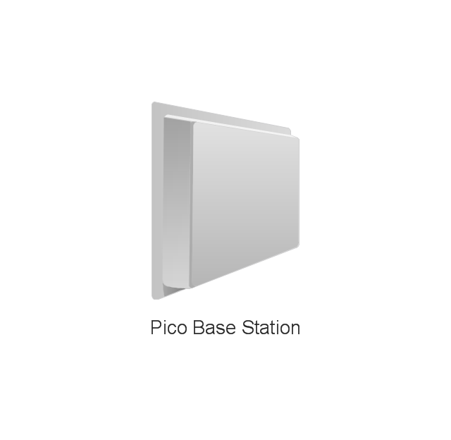
The vector stencils library "Tranzeo" contains 13 clipart icons of Tranzeo devices for drawing computer network diagrams and telecommunication equipment layouts.
"Tranzeo Wireless Technologies Inc. ... leads the wireless broadband industry as a premier manufacturer of high-performance wireless network equipment...
Tranzeo's full spectrum of point-to-point and point-to-multipoint radios, WiMAX equipment, and mesh network solutions are designed for wireless internet service providers, governments, campuses, military, carriers, enterprise customers, and systems integrators..." [tranzeo.com]
The clip art example "Tranzeo - Vector stencils library" was created using the ConceptDraw PRO diagramming and vector drawing software extended with the Telecommunication Network Diagrams solution from the Computer and Networks area of ConceptDraw Solution Park.
www.conceptdraw.com/ solution-park/ computer-networks-telecommunication
Data modeling with ConceptDraw PRO
Data modelling will help you to study and analyze business processes in your organization for optimization and increase of effectiveness and production.The vector stencils library "Telecommunication networks" contains 32 clipart images of telecommunication network devices and equipment for drawing telecom network diagrams.
"A telecommunications network is a collection of terminal nodes, links and any intermediate nodes which are connected so as to enable telecommunication between the terminals.
The transmission links connect the nodes together. The nodes use circuit switching, message switching or packet switching to pass the signal through the correct links and nodes to reach the correct destination terminal.
Each terminal in the network usually has a unique address so messages or connections can be routed to the correct recipients. The collection of addresses in the network is called the address space." [Telecommunications network. Wikipedia]
The clip art example "Telecommunication networks - Vector stencils library" was created using the ConceptDraw PRO diagramming and vector drawing software extended with the Telecommunication Network Diagrams solution from the Computer and Networks area of ConceptDraw Solution Park.
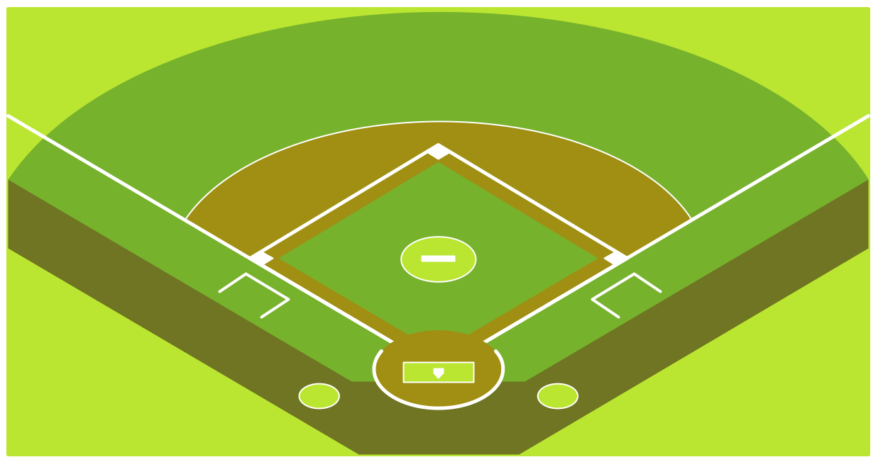
Baseball Diagram – Baseball Field – Corner View – Template
ConceptDraw PRO extended with the Baseball solution provides access to libraries, templates and samples allows creating baseball diagrams and schemas. Fields objects are designed according to real fields dimensions. A set of fields samples includes dimensions. All plays and positions diagrams are available as ready-to-modify samples.- Crow's foot ERD - Educational data base | Entity-Relationship ...
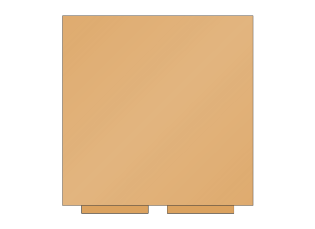
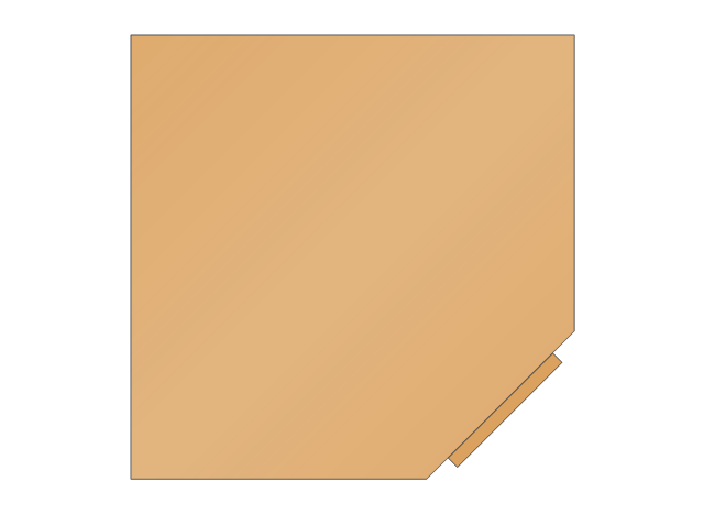
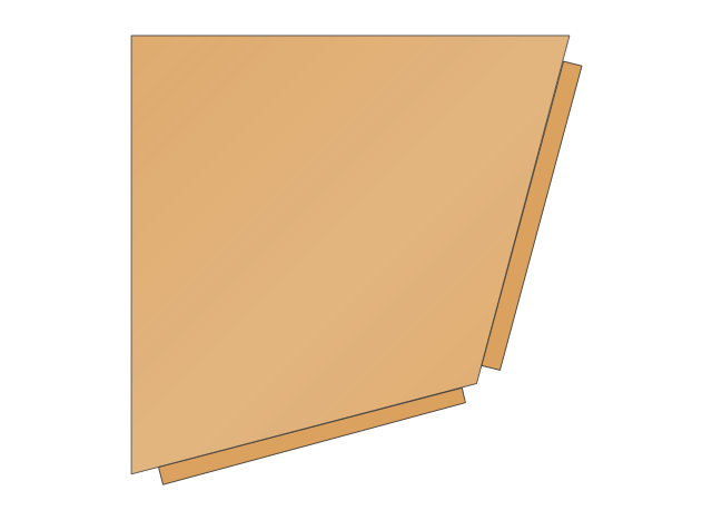
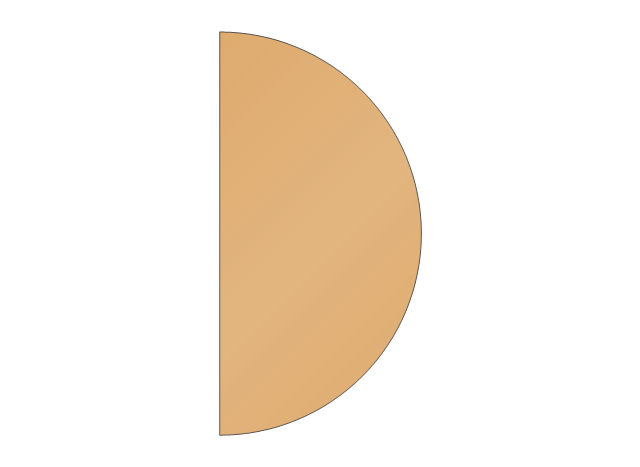
- Design elements - Cabinets and bookcases | Office space plan ...
- Basic Flowchart Symbols and Meaning | Process Flowchart | Audit ...
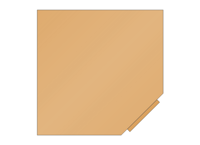
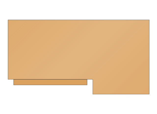
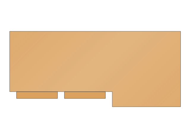
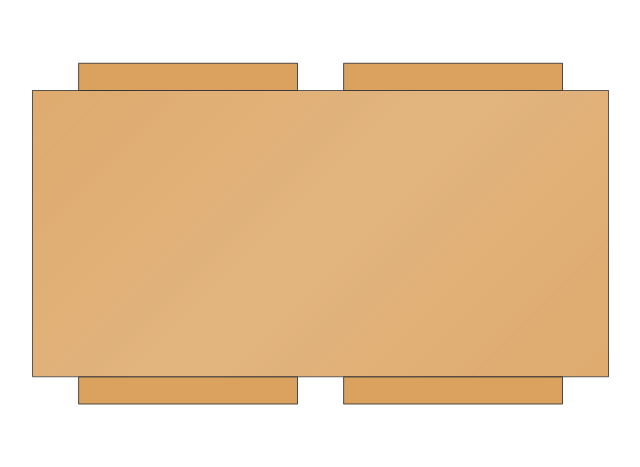
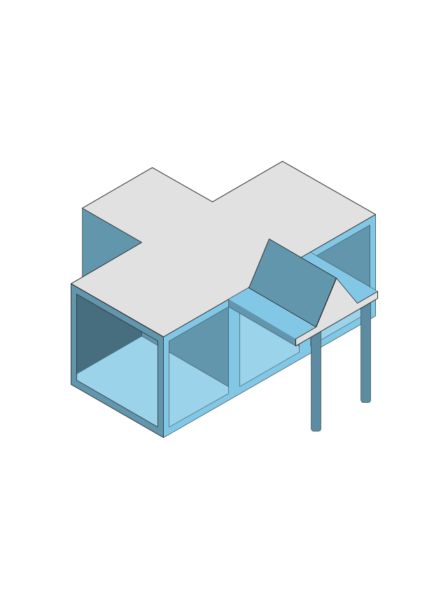
- Design elements - Cabinets and bookcases | Base Cabinet End Shelf
- Telecommunication Network Diagrams | Design elements ...
- Fishbone Diagram | Crow's foot ERD - Educational data base ...
- What Is The Base Of Human Development Flow Chart
- Design elements - ER diagram (Chen notation) | Crow's foot ERD ...
- Diagram Of Triangular Base Pyramid
- Design elements - Cabinets and bookcases | Cabinets and ...
- Crow's foot ERD - Educational data base
- Base Peninsula 1
- Base blind corner
- Base End-Shelf
- Diagramming software for Amazon Web Service icon set: Data Base ...
- Flowchart Of Knowledge Base
- Base station
- CCTV Surveillance System Diagram. CCTV Network Diagram ...
- Network Glossary Definition | Equipment For Mordern Base Station ...
- Data Flow Diagram Of Library Catalogue Including Data Base
















-wireless-networks---vector-stencils-library.png--diagram-flowchart-example.png)













-wireless-networks---vector-stencils-library.png--diagram-flowchart-example.png)
-wireless-networks---vector-stencils-library.png--diagram-flowchart-example.png)


-tranzeo---vector-stencils-library.png--diagram-flowchart-example.png)
