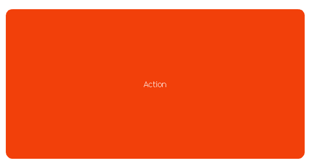
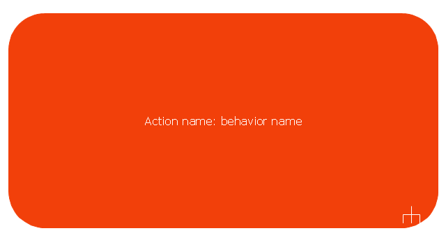
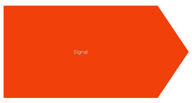
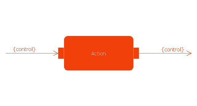
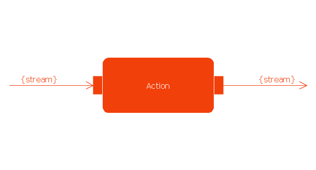
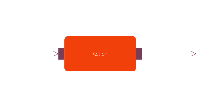
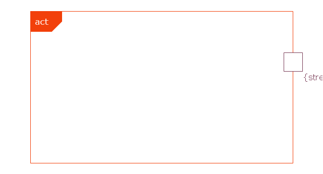
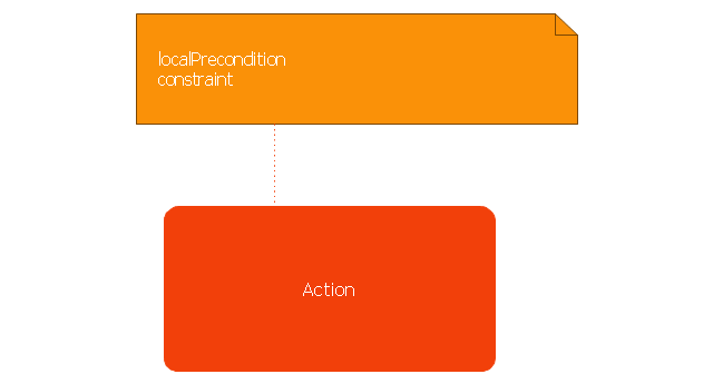
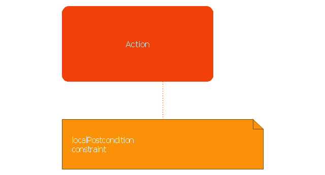
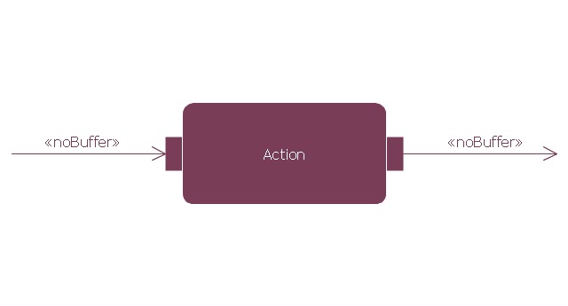
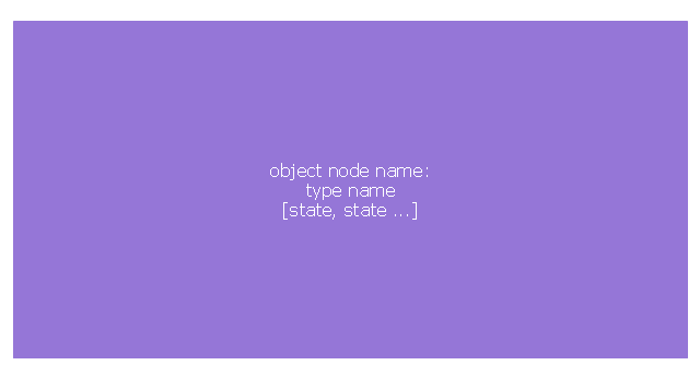
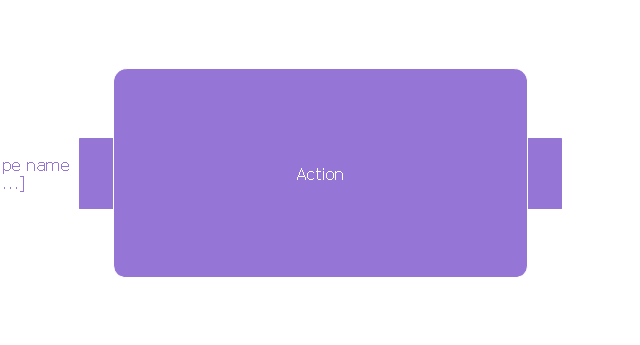
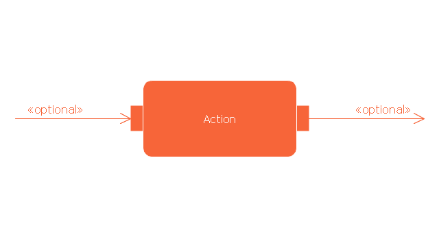
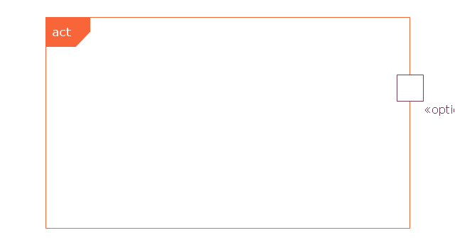
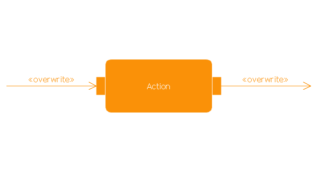
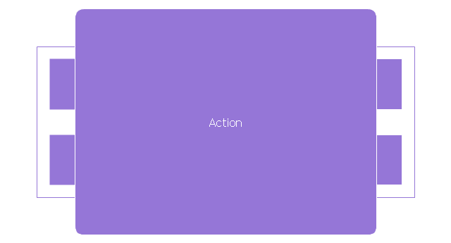
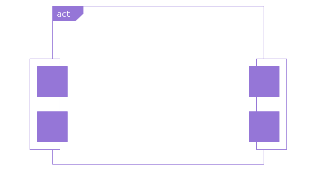
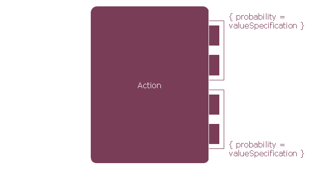
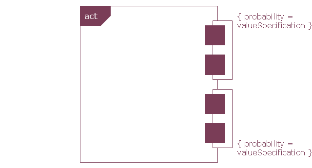
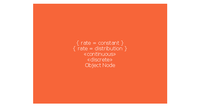
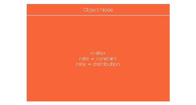
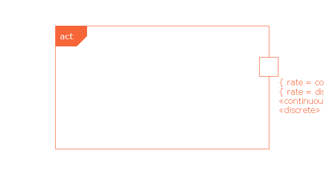
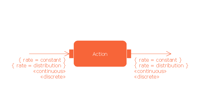
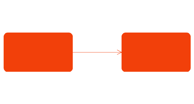
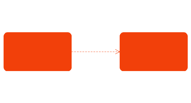
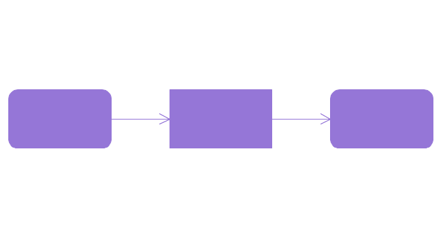
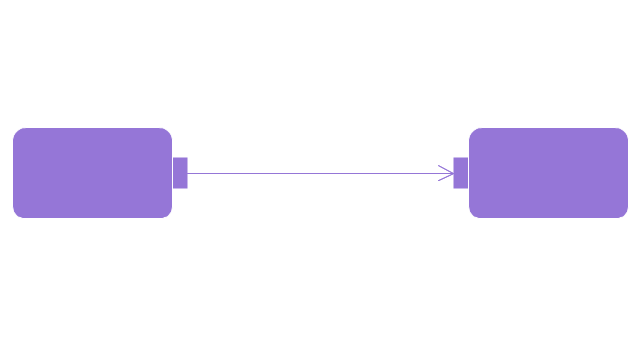
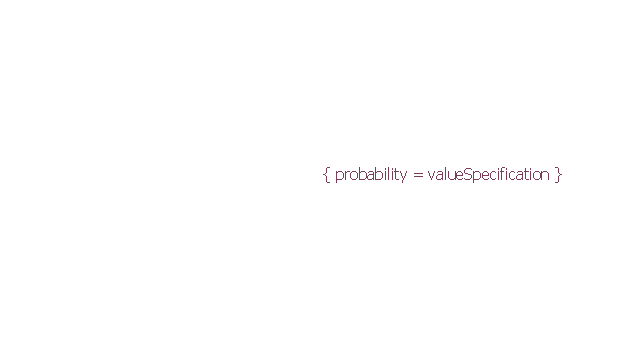
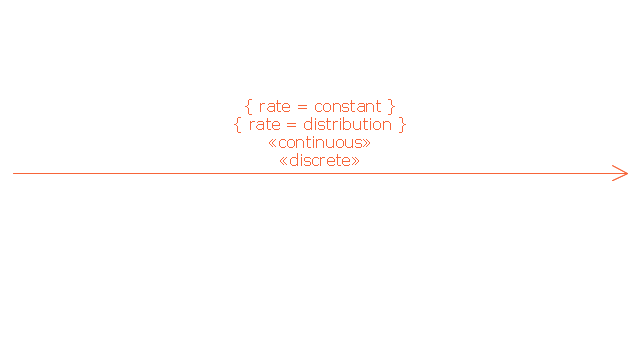
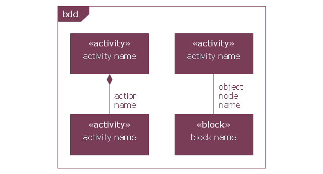
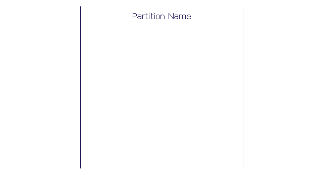
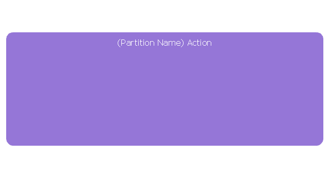
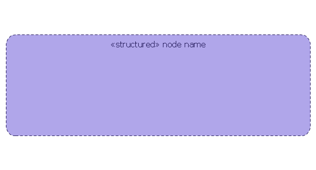
This vector stencils library contains 47 SysML activity diagram symbols.
Use it to design your SysML activity diagrams using ConceptDraw PRO diagramming and vector drawing software.
"Activity diagrams are constructed from a limited number of shapes, connected with arrows. The most important shape types:
- rounded rectangles represent actions;
- diamonds represent decisions;
- bars represent the start (split) or end (join) of concurrent activities;
- a black circle represents the start (initial state) of the workflow;
- an encircled black circle represents the end (final state).
Arrows run from the start towards the end and represent the order in which activities happen." [Activity diagram. Wikipedia]
The vector stencils library "Activity diagram" is included in the SysML solution from the Software Development area of ConceptDraw Solution Park.
UML Activity Diagram. Design Elements
UML Activity Diagram illustrate the business and operational step-by-step workflow of components in a system and shows the overall flow of control.
This vector stencils library contains 47 SysML activity diagram symbols.
Use it to design your SysML activity diagrams using ConceptDraw PRO diagramming and vector drawing software.
"Activity diagrams are constructed from a limited number of shapes, connected with arrows. The most important shape types:
- rounded rectangles represent actions;
- diamonds represent decisions;
- bars represent the start (split) or end (join) of concurrent activities;
- a black circle represents the start (initial state) of the workflow;
- an encircled black circle represents the end (final state).
Arrows run from the start towards the end and represent the order in which activities happen." [Activity diagram. Wikipedia]
The vector stencils library "Activity diagram" is included in the SysML solution from the Software Development area of ConceptDraw Solution Park.
Use it to design your SysML activity diagrams using ConceptDraw PRO diagramming and vector drawing software.
"Activity diagrams are constructed from a limited number of shapes, connected with arrows. The most important shape types:
- rounded rectangles represent actions;
- diamonds represent decisions;
- bars represent the start (split) or end (join) of concurrent activities;
- a black circle represents the start (initial state) of the workflow;
- an encircled black circle represents the end (final state).
Arrows run from the start towards the end and represent the order in which activities happen." [Activity diagram. Wikipedia]
The vector stencils library "Activity diagram" is included in the SysML solution from the Software Development area of ConceptDraw Solution Park.
IDEF4 Standard
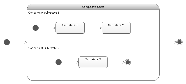
Use Case Diagrams technology. IDEF4 standard implies not only graphical presentation but the additional information about diagrams of heredity, methods systematization and types which are contained in specifications."State machine diagram is a behavior diagram which shows discrete behavior of a part of designed system through finite state transitions. State machine diagrams can also be used to express the usage protocol of part of a system. Two kinds of state machines defined in UML 2.4 are:
(1) behavioral state machine, and
(2) protocol state machine.
The following nodes and edges are typically drawn in state machine diagram: behavioral state, behavioral transition, protocol state, protocol transition, different pseudostates. ...
Behavioral state machine is specialization of behavior and is used to specify discrete behavior of a part of designed system through finite state transitions. The state machine formalism used in this case is an object-based variant of Harel statecharts.
Behavior is modeled as a traversal of a graph of state nodes connected with transitions. Transitions are triggered by the dispatching of series of events. During the traversal, the state machine could also execute some activities. ...
Protocol state machine is a specialization of behavioral state machine and is used to express usage protocol or lifecycle of a classifier. It specifies which operations of the classifier can be called in which state and under which condition, thus specifying the allowed call sequences on the classifier’s operations. Protocol state machines express the legal transitions that a classifier can trigger." [uml-diagrams.org/ state-machine-diagrams.html]
The template "UML state machine diagram" for the ConceptDraw PRO diagramming and vector drawing software is included in the Rapid UML solution from the Software Development area of ConceptDraw Solution Park.
www.conceptdraw.com/ solution-park/ software-uml
UML Collaboration Diagram. Design Elements
UML Collaboration Diagram illustrates how components are wired together to larger components and software systems that shows the structure of arbitrarily complex systems.ConceptDraw has 393 vector stencils in the 13 libraries that helps you to start using software for designing your own UML Diagrams. You can use the appropriate stencils of UML notation from UML Collaboration library with 36 objects
HelpDesk
How to Operate a Multiple Main Idea on Your Mind Map
If you are using multiple Main Ideas your maps, it is necessary to know that there is a difference in behavior between the original primary Main Idea and the other Ideas you add.Workflow Diagram Software Mac
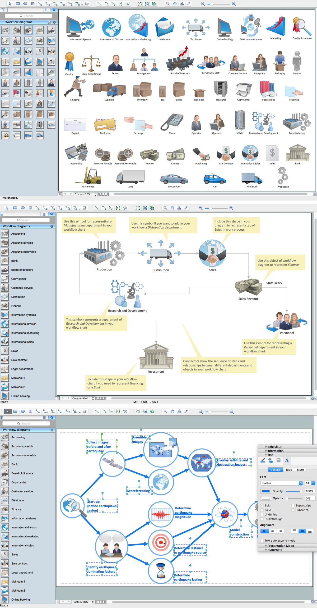
ConceptDraw PRO software is the best Mac software for drawing workflow diagrams. Its rich set of samples and templates, and specific features to draw diagrams faster make this software as comfortable as possible for drawing workflow diagrams.Use the ConceptDraw PRO professional Mac OS X software for drawing workflow diagram. The Workflow Diagrams solution with its libraries and templates set make the possibility to identify resources that are required for work goal implementation. The process flow diagram identify flow which occurs as network of process dependencies, organizational decisions and interactions between departments. Usually workflow diagrams show business participants actions that carry product or service to the final destination, the consumer.
"Surveillance is the monitoring of the behavior, activities, or other changing information, usually of people for the purpose of influencing, managing, directing, or protecting them. This can include observation from a distance by means of electronic equipment (such as CCTV cameras), or interception of electronically transmitted information (such as Internet traffic or phone calls); and it can include simple, relatively no- or low-technology methods such as human intelligence agents and postal interception. ...
Surveillance is very useful to governments and law enforcement to maintain social control, recognize and monitor threats, and prevent/ investigate criminal activity. With the advent of programs such as the Total Information Awareness program and ADVISE, technologies such as high speed surveillance computers and biometrics software, and laws such as the Communications Assistance For Law Enforcement Act, governments now possess an unprecedented ability to monitor the activities of their subjects." [Surveillance. Wikipedia]
[itl.nist.gov/ iad/ 894.01/ tests/ avss/ 2009/ ]
The example "Camera layout schematic" was created using the ConceptDraw PRO diagramming and vector drawing software extended with the Security and Access Plans solution from the Building Plans area of ConceptDraw Solution Park.
- Activity on Node Network Diagramming Tool | Program Evaluation ...
- UML activity diagram - Cash withdrawal from ATM | UML Tool ...
- Vector stencils library - Activity diagram
- Design elements - UML activity diagrams | Cross-Functional ...
- Activity on Node Network Diagramming Tool | Network Analysis ...
- Expanded objects BPMN 1.2 - Vector stencils library | Expanded ...
- Diagramming Software for Design UML State Machine Diagrams ...
- How to make great presentation via Skype? ...how it works with ...
- UML State Machine Diagram.Design Elements | Finite State ...
- Behavioral Uml Diagrams
- UML Activity Diagram | Diagramming Software for Design UML ...
- Cross-Functional Flowcharts
- Diagramming Software for designing UML Sequence Diagrams ...
- Block diagram - Types of individual behavior in organization ...
- Basic Diagramming | Block diagram - Types of individual behavior in ...
- Computer Network Diagrams | Examples of Flowcharts, Org Charts ...
- UML Package Diagram. Design Elements | Diagramming Software ...
- Flowchart Software | Process Flowchart | Flowchart Program Mac ...
- Design elements - Gateways BPMN 2.0
- Diagramming Software for Design UML Activity Diagrams | UML ...
