HelpDesk
How to Create Flowchart Using Standard Flowchart Symbols
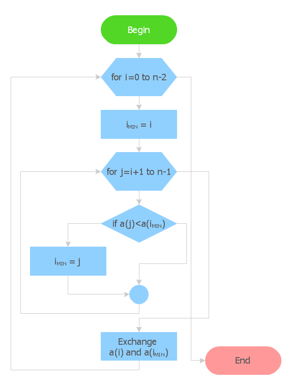
Flowcharts are used to display an algorithm for consistent execution of certain steps. Flowchart is probably the easiest way to make a graphical representation of any process. Flowcharts use the set of standard geometric symbols and arrows to define relationships. ConceptDraw PRO allows you to create professional flowchart quickly and easily. The ability to create flowcharts is contained in the Flowcharts solution. The solution provides a set of special tools for creating flowcharts.
 ConceptDraw Solution Park
ConceptDraw Solution Park collects graphic extensions, examples and learning materials
 Chemical and Process Engineering
This chemical engineering solution extends ConceptDraw PRO v.9.5 (or later) with process flow diagram symbols, samples, process diagrams templates and libraries of design elements for creating process and instrumentation diagrams, block flow diagrams (BFD
HelpDesk
How to Draw a Chemical Process Flow Diagram
Process Flow Diagram widely used in modeling of processes in the chemical industry. A Chemical Process Flow diagram (PFD) is a specialized type of flowchart. With the help of Chemical Process Flow Diagram engineers can easily specify the general scheme of the processes and chemical plant equipment. Chemical Process Flow Diagram displays the real scheme of the chemical process, the relationship between the equipment and the technical characteristics of the process. Chemical Process Flow Diagram illustrates the connections between the basic equipment as well as the overall structure of pipelines and other supporting equipment. The purpose of the PFD is to build the image of the basic idea of the chemical process. ConceptDraw PRO together with its Chemical and Process Engineering solution delivers the possibility to design Chemical Process Flow diagrams. It is designed for chemical industry engineers and designers.HelpDesk
How to Create a Data Flow Diagram using ConceptDraw PRO
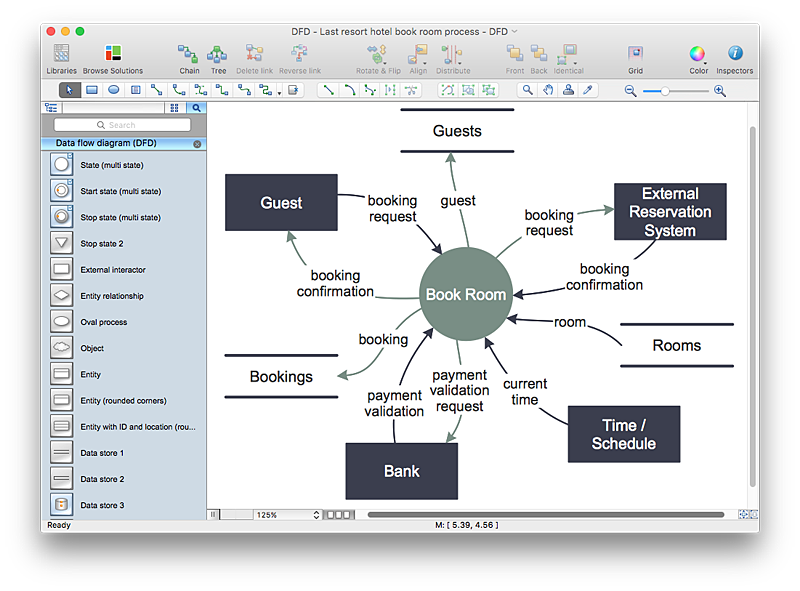
Data flow diagramming is a highly effective technique for showing the flow of information through a system. Data flow diagrams reveal relationships among and between the various components in a program or system. DFD is an important technique for modeling a system’s high-level detail by showing how input data is transformed to output results through a sequence of functional transformations. The set of standard symbols is used to depict how these components interact in a system. ConceptDraw PRO allows you to draw a simple and clear Data Flow Diagram using special libraries.- Computer Manufacturing Process Flow Chart
- Flow Chat For Computer Project
- Flow Charts And Model Computer Science
- DFD Flowchart Symbols | Computer Network Diagrams | Interactive ...
- Process Flow Diagram Of A Computer Software
- Basic Flowchart Symbols and Meaning | Process Flowchart ...
- Computer Data Flow Chart
- Proces Of Flow Chart Computer
- Basic Flowchart Symbols and Meaning | Flow chart Example ...
- Basic Flowchart Symbols and Meaning | The Original Diagram Flow ...
- Flow Chart Of Computer Graphics
- Computer Systerm Disign Flow Chart
- Flow Chart Of Computer Aided Design
- Computer Project With Flow Chart
- Program to Make Flow Chart | Basic Flowchart Symbols and ...
- Entity Relationship Diagram Symbols | Data Flow Diagram Symbols ...
- Basic Flowchart Symbols and Meaning | Process Flowchart ...
- Computer System Is Design In Formed At Flow Charting To Help
- Data Flow Diagram And Flowchart Of A Computer Program
- Flow Chart Of Operating System Of Computer


