SysML
Systems Modeling Language (SysML) is a general-purpose modeling language for systems engineering applications. ConceptDraw PRO diagramming and vector drawing software was extended with SysML Solution from the Software Development Area of ConceptDraw Solution Park specially to help systems engineers design various model systems with SysML.Mind Map Food
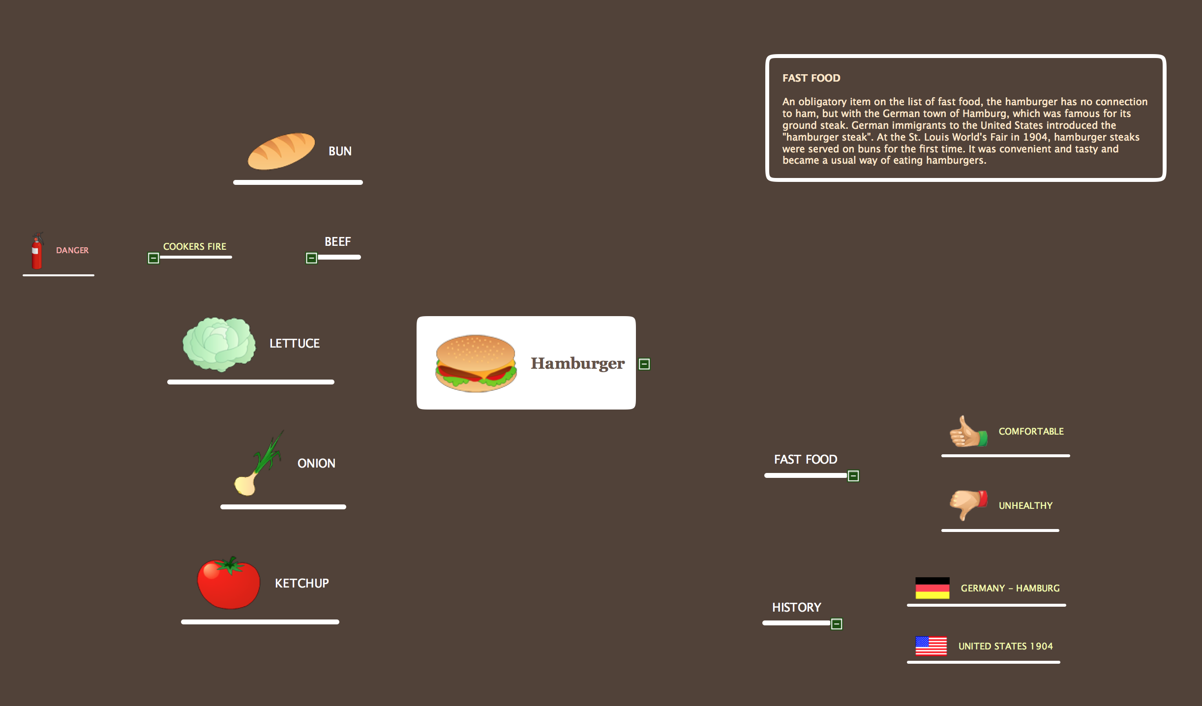
ConceptDraw MINDMAP from ConceptDraw Office suite is versatile, powerful and at the same time easy-to-use tool for brainstorming, project planning, organizing ideas and data, meeting management, note taking, etc. It lets quickly create the Mind Maps that intuitively illustrate the thought process and offers for using wide variety of document styles and formats. ConceptDraw MINDMAP delivers its users the perfect possibility of exporting constructed Mind Maps, of easy making MS PowerPoint presentations from the Mind Maps, of publishing the images and maps to Twitter and creating the illustrated tweet story. ConceptDraw MINDMAP application offers the powerful tools for designing the maps for any thematic, including the cooking. You can visually represent any recipe, the needed ingredients and steps of preparation some dishes, tell about the recipe's history, compose the menu for day, week, month, depict the basic information about any cuisine in the world. It is convenient to use the possibility of easy making different Mind Maps when making the menu for restaurants, cafes, fast food factories, etc.
 ATM UML Diagrams
The ATM UML Diagrams solution lets you create ATM solutions and UML examples. Use ConceptDraw PRO as a UML diagram creator to visualize a banking system.
Model Based Systems Engineering
ConceptDraw PRO is a professional diagramming and vector drawing software. Now, enhanced with SysML Solution from the Software Development Area of ConceptDraw Solution Park, ConceptDraw PRO became an ideal software for model based systems engineering (MBSE).
 SYSML
SYSML
The SysML solution helps to present diagrams using Systems Modeling Language; a perfect tool for system engineering.
Banking System
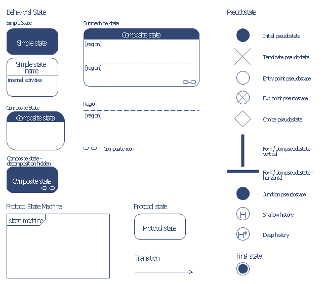
ConceptDraw PRO extended with ATM UML Diagrams Solution from the Software Development Area of ConceptDraw Solution Park is a powerful software for representing the ATM processes, for designing and building banking system and ATMs.The vector stencils library "Bank UML state machine diagram" contains 21 shapes for drawing UML state machine diagrams.
Use it for object-oriented modeling of your bank information system.
"The state diagram in the Unified Modeling Language is essentially a Harel statechart with standardized notation, which can describe many systems, from computer programs to business processes. In UML 2 the name has been changed to State Machine Diagram. The following are the basic notational elements that can be used to make up a diagram:
* Filled circle, pointing to the initial state.
* Hollow circle containing a smaller filled circle, indicating the final state (if any).
* Rounded rectangle, denoting a state. Top of the rectangle contains a name of the state. Can contain a horizontal line in the middle, below which the activities that are done in that state are indicated.
* Arrow, denoting transition. The name of the event (if any) causing this transition labels the arrow body. A guard expression may be added before a "/ " and enclosed in square-brackets ( eventName[guardExpression] ), denoting that this expression must be true for the transition to take place. If an action is performed during this transition, it is added to the label following a "/ " ( eventName[guardExpression]/ action ).
* Thick horizontal line with either x>1 lines entering and 1 line leaving or 1 line entering and x>1 lines leaving. These denote join/ fork, respectively." [State machine diagram. Wikipedia]
This example of UML state machine diagram symbols for the ConceptDraw PRO diagramming and vector drawing software is included in the ATM UML Diagrams solution from the Software Development area of ConceptDraw Solution Park.
- Vector stencils library - State machine diagram | Design elements ...
- Vector stencils library - Activity diagram | Vector stencils library ...
- UML State Machine Diagram.Design Elements | Design elements ...
- UML State Machine Diagram.Design Elements
- Human Resources Hiring Flowchart Example
- Mechanical Drawing Symbols | Design elements - Bearings ...
- Design elements - Bearings | Bearings - Vector stencils library ...
- Ring Network Topology | Design elements - Meter indicators | IP ...
- Soccer (Football) Positions | Soccer (Football) Tactics | Association ...
- Process Flow Diagram Symbols | Design elements - Vessels ...
- UML Diagram | State Diagram Example - Online Store | UML State ...
- Soccer (Football) Offside | Association football (soccer) offside | Ice ...
- Soccer (Football) Tactics | Soccer | Soccer (Football) Diagram ...
- Soccer (Football) Positions | Soccer (Football) Formation | Soccer ...
- Soccer | Soccer (Football) Dimensions | Create Soccer (Football ...
- State Diagram Example - Online Store | UML state machine diagram ...
- Association football (soccer) positions | Association football (soccer ...
- State Machine Diagram | Bank UML Diagram | ATM UML Diagrams ...
- State Machine Diagram | Diagramming Software for Design UML ...
- State Transition Diagram


